4. Remove the battery (see Battery on page 33).
5. Remove the keyboard (see
Keyboard on page 37).
6. Remove the top cover (see
Top cover on page 40).
7. Remove the hard drive (see
Hard drive on page 44).
8. Remove the USB board (see
USB board/Audio jack on page 47).
9. Remove the WLAN (see
WLAN module on page 48).
10. Remove the system board (see
System board on page 51).
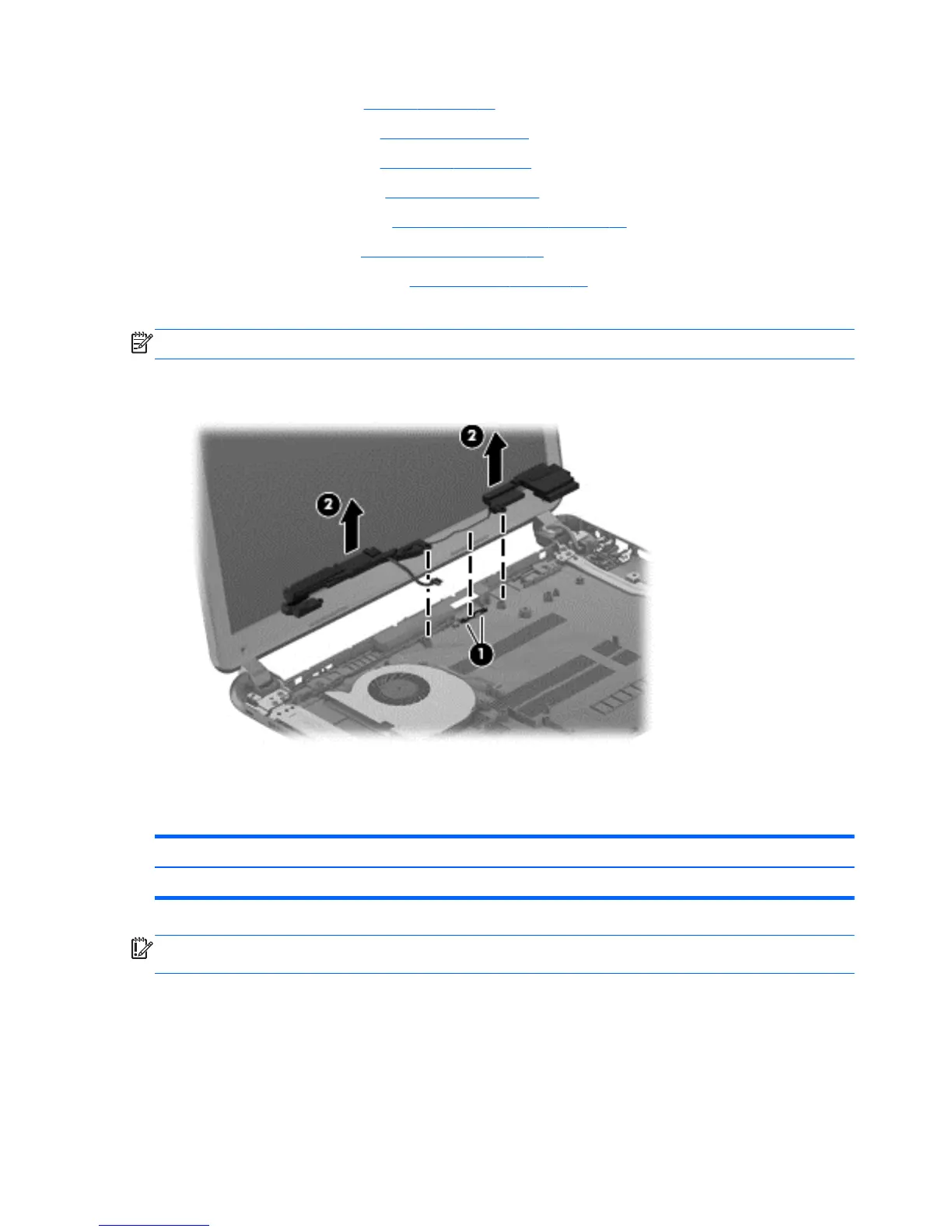
Remove the speaker assembly:
NOTE: The speaker screws were removed during the process to remove the top cover.
▲
Gently release the wires (1) routed along the top of the base enclosure and lift both pieces of the
speaker assembly (2).
Reverse this procedure to install the speaker assembly on the base enclosure.
RJ-45 cover
Description Spare part number
RJ-45 cover 700428-001
IMPORTANT: Make special note of each screw and screw lock size and location during removal
and replacement.
Before removing the RJ-45 cover, follow these steps:
1. Shut down the computer.
2. Disconnect all external devices connected to the computer.
3. Disconnect the power from the computer by first unplugging the power cord from the AC outlet
and then unplugging the AC adapter from the computer.
66 Chapter 4 Removal and replacement procedures
 Loading...