Remove the heat sink assembly:
1. Turn the system board upside down, with the front toward you.
NOTE: Steps 3 through 5 apply to computer models equipped with a graphics subsystem with
discrete memory. See steps 6 and 8 for fan/heat sink assembly removal information for computer
models equipped with a graphics subsystem with UMA memory.
2. Disconnect the fan cable from the system board.
NOTE: Steps 3 through 5 apply to computer models equipped with a graphics subsystem with
discrete memory. See steps 6 and 8 for fan/heat sink assembly removal information for computer
models equipped with a graphics subsystem with UMA memory.
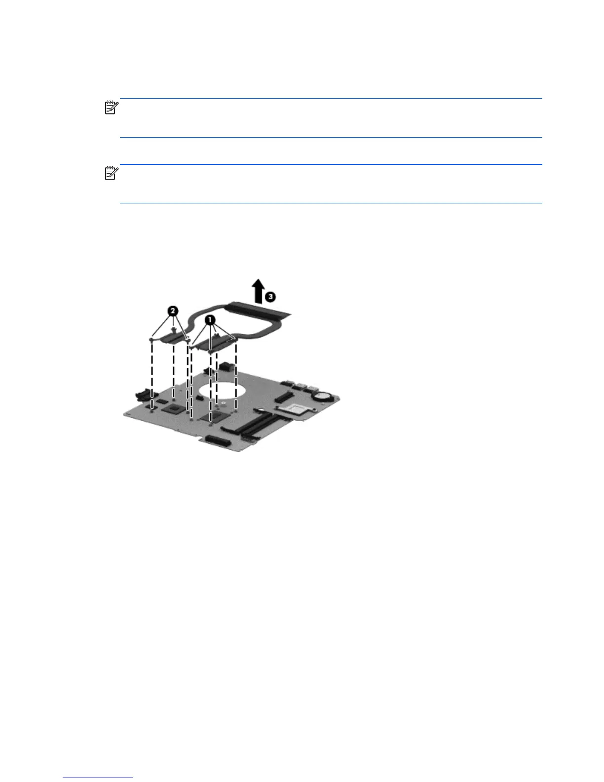
3. Following the 1, 2, 3, 4, 5, 6, 7 sequence stamped into the fan/heat sink assembly, loosen
the four Phillips M2.0×10.0 captive screws (1) and the three Phillips M2.0×3.5 captive screws
(2) that secure the fan/heat sink assembly to the system board.
4. Remove the heat sink assembly (3) from the system board.
88 Chapter 6 Removal and replacement procedures for Authorized Service Provider parts