3.
Disconnect the power from the computer by first unplugging the power cord from the AC outlet,
and then unplugging the AC adapter from the computer.
4. Remove the battery (see
Battery on page 50).
5. Remove the following components:
a. Hard drive (see
Hard drive on page 60)
b. Optical drive (see
Optical drive on page 57)
c.
Keyboard (see
Keyboard on page 66)
d. Modem module (see
Modem module on page 72)
e. Fan (see
Fan on page 76)
f. Heat sink (see
Heat sink on page 78)
g. Base enclosure cover (see
Base enclosure cover on page 82)
h. Display assembly (see
Display assembly on page 89)
i. System board (see
System board on page 96)
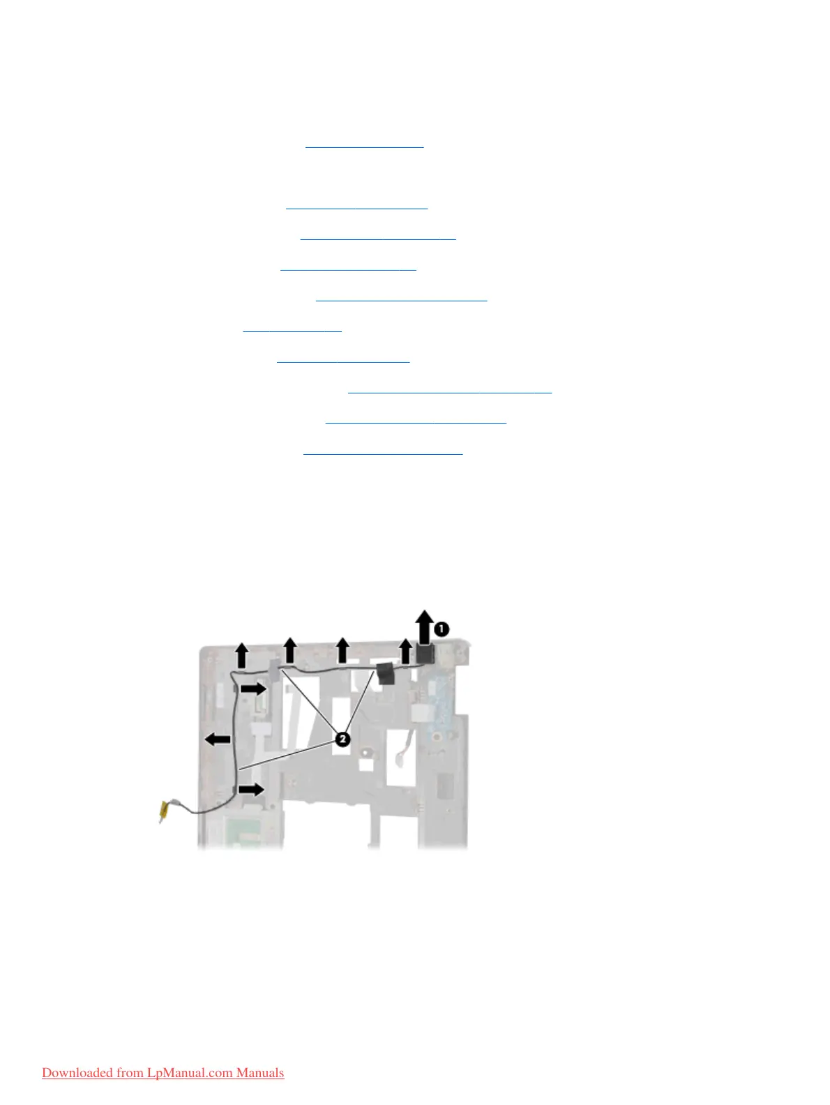
Remove the RJ-11 connector cable:
1. Position the top cover upside-down, with the front toward you.
2.
Remove the RJ-11 connector (1) from the clip built into the top cover.
3.
Remove the RJ-11 connector cable from the clips and routing channel (2) built into the top cover.
4. Remove the RJ-11 connector cable from the top cover.
Reverse this procedure to install the RJ-11 connector cable.
106 Chapter 4 Removal and replacement procedures
Downloaded from LpManual.com Manuals
 Loading...