7-3
Planning and Implementation for the 2910al PoE+ Switches
Planning Your PoE Configuration
Planning and
Implementation for the
2910al PoE+ Switches
The table in this example configuration contains entries that show the PoE+
power available for the 2910al-24G-PoE+ when connecting to an external
power supply.
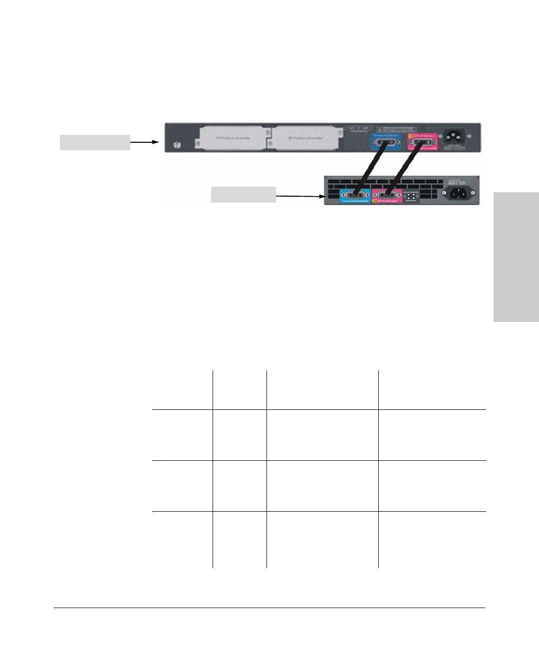
Figure 7-2. Example of a 2910al-24G-PoE+ Switch connecting to a 630 RPS/EPS
The same considerations apply for the mini-GBIC ports as in the previous
example.
One 2910al-24G-PoE switch can be supported by one 630 RPS/EPS. This is a
full redundant configuration. The switch can be supplied with power should
either of their internal power supplies fail. The 630 RPS/EPS can supply system
power to keep the switch powered on and PoE+ power to supply the attached
PoE+ devices with power.
2910al 24 port switch
630 RPS/EPS
Source of
Power
Watts
Available
# of Ports Powered and
Average watts/Port from
internal supply
Redundant # of Ports
Powered and Average
watts/Port
Internal PoE+
Power Supply
382 12 @ average 30W each for a
total of 360 W
24 @ average 15.4 W each
24 @ average 7.5 W each
None
Internal plus
External PoE+
Power Supply
382 + 382 24 @ average 30.0 W each for
a total of 720
24 @ average 15.4 W each
24 @ average 7.5 W each
12 @ average 30.0 W each
for a total of 360 W
24 @ average 15.4 W each
24 @ average 7.5 W each
External PoE+
Power Supply
(failed Internal
PoE Power
Supply)
382 12 @ average 30W each for a
total of 360 W
24 @ average 15.4 W each
24 @ average 7.5 W each
None

 Loading...