IP Routing Features
Configuring OSPF
OSPF Area 0
OSPF Area 1
“transit area”
OSPF Area 2
HP 5308xl
HP 5308xl “A”
Router ID 10.0.0.1
HP 5308xl “C”
Router ID 209.157.22.1
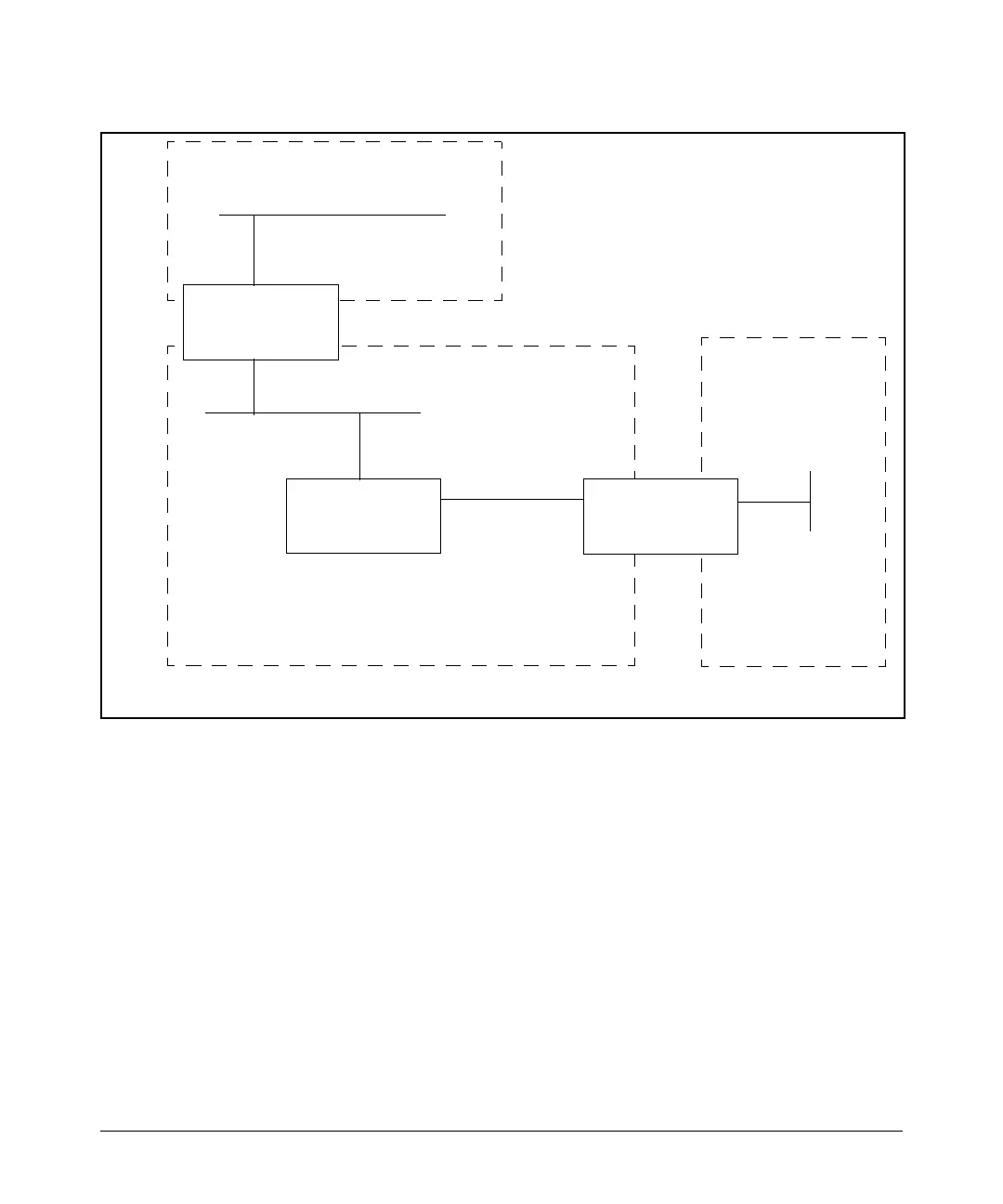
Figure 11-9. Defining OSPF virtual links within a network
Example. Figure 11-9 shows an OSPF area border router, Routing
Switch-A, that is cut off from the backbone area (Area 0). To provide backbone
access to Routing Switch-A, you can add a virtual link between Routing
Switch-A and Routing Switch-C using Area 1 as a transit area. To configure the
virtual link, you define the link on the router that is at each end of the link. No
configuration for the virtual link is required on the routers in the transit area.
To configure the virtual link on Routing Switch-A, enter the following
commands:
HPswitch(ospf)# area 1 virtual-link 209.157.22.1
HPswitch(ospf)# write memory
11-46
 Loading...