Do you have a question about the HP ProLiant DL380 Gen10 Plus and is the answer not in the manual?
Instructions for removing the system's top cover using the hood latch mechanism.
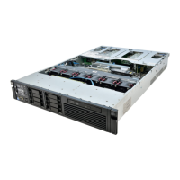
Procedure to detach the fan cage module, air baffle, and riser cage from the system.
Guidance on removing the lithium battery using a medium flat head screwdriver.
Instructions for removing the Mega-cell HSTNS-BB05 component from the system.
Detach bracket with PCA (LFF) or HDD cage with PCA (SFF) using a Torx T15 driver.
Procedure for safely removing the power supply unit(s) from the system.
Detach the system board and its tray using a Torx T15 driver and thumbscrews.
Instructions for removing the riser card, which is a Printed Circuit Assembly (PCA).
Detach the Hard Disk Drive Backplane (PCA) from its bracket or cage.
Remove the system board (PCA) from its tray using specific Torx and socket drivers.
Guidance on removing specific electrolytic capacitors from various power supply models.
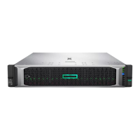
This document outlines the end-of-life disassembly instructions for HPE ProLiant DL380 Gen10 Plus servers, providing a guide for recyclers and treatment facilities to remove components and materials requiring selective treatment as defined by Directive 2012/19/EU (WEEE). The primary function of this document is to facilitate responsible recycling and disposal by detailing the selective treatment items and the necessary disassembly steps.
The server is designed with various components that require specific handling at the end of its life cycle. These include printed circuit boards (PCBs) or printed circuit assemblies (PCAs) with a surface area greater than 10 sq cm, all types of batteries (including standard alkaline and lithium coin or button style batteries), mercury-containing components (such as lamps, display backlights, scanner lamps, and switches), liquid crystal displays (LCDs) with a surface greater than 100 sq cm (including those with gas discharge lamps), cathode ray tubes (CRTs), capacitors/condensers containing PCB/PCT, electrolytic capacitors/condensers measuring greater than 2.5 cm in diameter or height, external electrical cables and cords, gas discharge lamps, plastics containing brominated flame retardants weighing more than 25 grams (excluding PCBs or PCAs already listed), components and parts containing toner and ink (including liquids, semi-liquids, gel/paste, cartridges, print heads, tubes, vent chambers, and service stations), and components and waste containing asbestos. The document specifies the quantity of each of these items found within the server, ensuring that recyclers are aware of the scope of selective treatment required. For instance, the server contains 8 PCBs/PCAs, 2 batteries, and 14 electrolytic capacitors/condensers meeting the specified size criteria.
The disassembly process is structured to be straightforward, requiring a set of common tools. The tools required for disassembly include a Torx driver (T15), a Phillips screwdriver (#2), a medium flathead screwdriver, and socket screwdrivers (5 mm and 8 mm). These tools are standard for electronics disassembly, making the process accessible to trained personnel at recycling facilities.
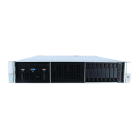
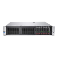
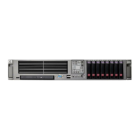
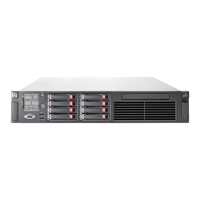
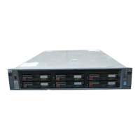
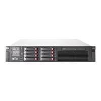
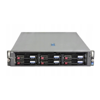
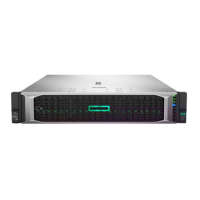
The disassembly process begins with the removal of the top cover, which is secured by a hood latch. This initial step provides access to the internal components. Following this, the Fan cage module, Air baffle, and Riser cage are removed from the system. These components are typically secured with screws and may require the use of a Torx driver. The document provides visual aids, such as diagrams for both LFF (Large Form Factor) and SFF (Small Form Factor) systems, to illustrate the location of these components and the method of removal.
A critical step in the selective treatment process is the removal of the lithium battery. This battery is typically secured and can be removed using a medium flathead screwdriver. The document highlights the importance of this step due to the specific recycling requirements for batteries. Another component requiring careful removal is the Mega-cell HSTNS-BB05, which is also part of the selective treatment items.
Further disassembly involves removing various brackets and cages that house printed circuit assemblies. For LFF systems, the bracket with PCA is removed, while for SFF systems, the HDD cage with PCA is removed. These steps involve unlocking screws with a Torx driver (T15). The power supply units are then removed from the system.
The system board with its tray is another key component that needs to be removed. This involves unlocking thumbscrews with a Torx driver (T15) and using 5 mm and 8 mm socket screwdrivers to remove additional screws securing the system board to its tray. The riser card (PCA) is also removed by unlocking screws with a Torx driver (T15). Similarly, the HDD BP (PCA) is removed from both the bracket in LFF systems and the HDD cage in SFF systems, again using a Torx driver (T15) to unlock the securing screws.
A significant part of the selective treatment process involves the removal of electrolytic capacitors from the power supply units. The document provides detailed instructions and images for identifying and removing these capacitors from various power supply models, including HSTNS-PD40, HSTNS-PD40-1, HSTNS-PL40, HSTNS-PL40-1, HSTNS-PC40, HSTNS-PC40-1, HSTNS-PD41, HSTNS-PD41-1, HSTNS-PL41, HSTNS-PL41-1, HSTNS-PC41, HSTNS-PC41-1, HSTNS-PD44, HSTNS-PD44-1, HSTNS-PL45, HSTNS-PL45-1, HSTNS-PL46-1, HSTNS-PF46-1, HSTNS-PR62, HSTNS-PL62, and HSTNS-PD70. Specific capacitor sizes and locations are highlighted, such as C801 (25mm55mm), C237, C238, C241 (10mm25mm), C102 (25mm25mm), BC1 (25mm60mm), C106, C107, C108 (10mm25mm), C102 (30mm30mm), C212, C233, C238 (10mm25mm), C101, C105, C106, C114, C115 (8mm20mm), C201, C202 (10mm38.5mm), C200 (26mm43mm), C250, C251 (13mm50mm), C12 (1.60mm25mm), and C328 (18mm*30mm). These capacitors are typically pried from the PCB using a medium flathead screwdriver and disposed of properly according to waste management guidelines.
The document emphasizes the importance of following these steps to ensure that all materials requiring selective treatment are correctly identified and removed, thereby contributing to environmentally sound recycling practices. The inclusion of optional graphics and detailed descriptions aims to make the disassembly process as clear and efficient as possible for recyclers. This systematic approach ensures compliance with WEEE directives and promotes the responsible management of electronic waste.
| Form Factor | 2U Rack |
|---|---|
| Management | HPE iLO 5 |
| Processor | Intel Xeon Scalable processors |
| Memory | HPE DDR4 SmartMemory |
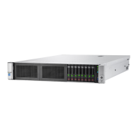
| Storage | 12 LFF drive bays |
| Network | HPE FlexibleLOM, optional stand-up cards |
| Power Supply | 800W, 1600W |
| Operating System Support | Microsoft Windows Server, Red Hat, SUSE, VMware ESXi |