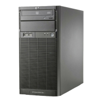
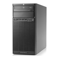
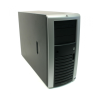
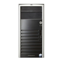
System Structure
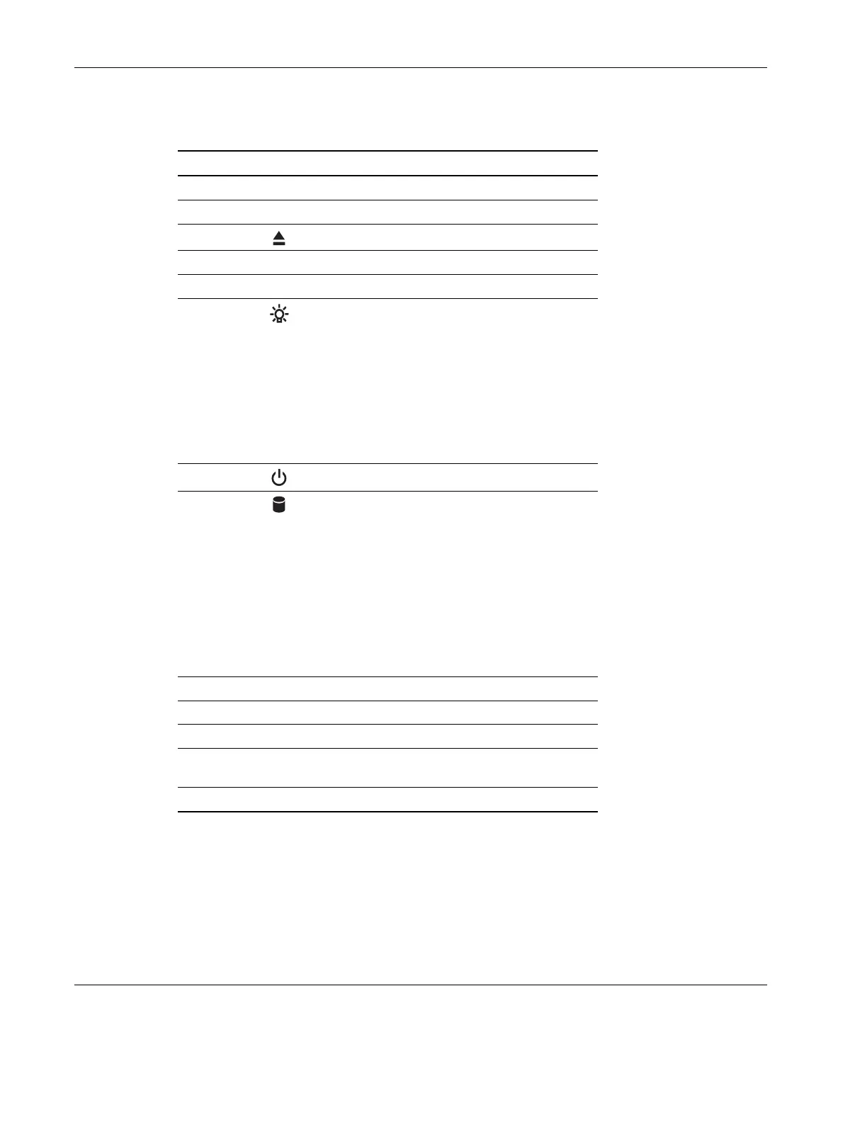
Table 2-1: Front Panel Components
Item Icon Description
1 CD-ROM drive
2 CD-ROM drive mechanical eject hole
3
CD-ROM drive eject button
4 CD-ROM drive activity indicator
5 Full-height common bays
6
Power indicator (green)
This LED indicator provides the power state
of the server.
• Steady green when the server is
operating normally.
• Blinking green when the server is in
Standby mode.
• Off when the server is powered off.
7
Power button
8
Drive activity indicator (amber)
This LED indicator shows the power state of
any IDE or SCSI device installed in the server
including CD-ROM drive(s), IDE hard disk
drives, and SCSI devices connected to the
SCSI controller board.
• Flickering amber during any IDE or SCSI
device activity.
• Off when there is no IDE or SCSI device
activity.
9 Floppy disk drive (FDD)
10 FDD activity indicator
11 FDD eject button
12 Torx
®
screws for the hard disk drive
(HDD) cage
13 HDD cage
2-2 HP ProLiant ML110 Server Operations and Maintenance Guide