TippingPoint 10/110/330 Hardware Installation and Safety Guide 17
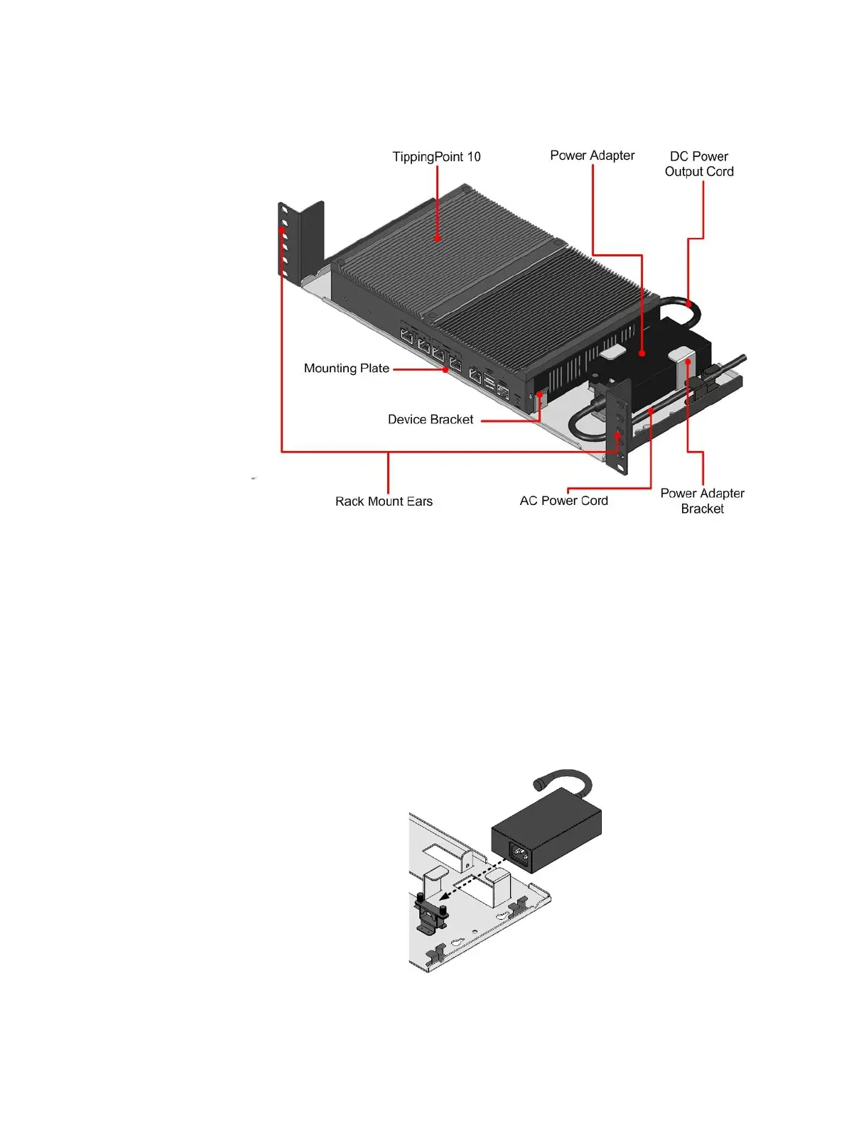
The following diagram shows the TippingPoint 10 on the fully-assembled mounting plate, with the rack ears
attached.
To attach the TippingPoint 10 to the mounting plate
1. Place the mounting plate on a flat surface.
2. Place the TippingPoint 10 between the device brackets on the mounting plate.
3. Secure the TippingPoint 10 to the device brackets with screws.
4. Loosen the screws that secure the top of the AC power cord sufficiently to allow the AC power cord
connector to pass through. (See Figure 3-5, “TippingPoint 10 Power Adapter Bracket,” on page 18.)
5. Ensure that the AC power cord is not attached to the power adapter and slide the adapter into the
bracket on the mounting plate: the power adapter in the power adapter bracket.
Figure 3-3 TippingPoint 10 Rack and Wall Mount Assembly
Figure 3-4 Placing the Power Adapter On the Mounting Plate
 Loading...