24 TippingPoint 110/330 Overview
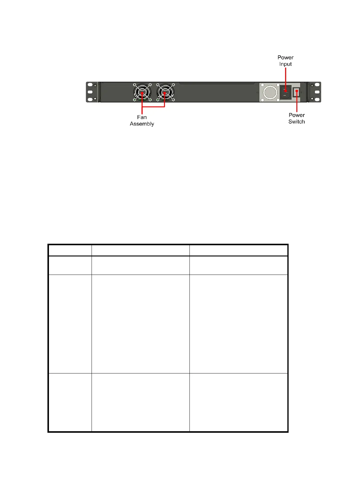
Figure 4-2 shows the chassis back panel for a TippingPoint 110/330.
The TippingPoint 110 and the TippingPoint 330 ship with the following pre-installed components:
• Four 10/100/1000 Gigabit Ethernet segments supporting up to:
• 100 Mbps aggregate across all segments on the TippingPoint 110
• 300 Mbps aggregate across all segments on the TippingPoint 330
• One 10/100/1000 Gigabit Ethernet management port
• One serial console RJ-45 port (Pinout: 1-RTS, 2-DTR, 3-TXD, 4-GND, 5-GND, 6- RXD, 7-DSR, 8-CTS)
• Two USB ports
LEDs
The following table describes the status LEDs used by the TippingPoint 110/330.
Figure 4-2 TippingPoint 110/330 - Back Panel
Table 4-1 TippingPoint 110/330 LEDs
LED Location Description
Power The right side of the front panel. Green: Indicates that the unit has
power and is running.
Device Status The right side of the front panel,
above the Power LED.
Off: No power, or the unit has been
shut down by CLI command.
Yellow: Unit is booting OR one of
the following faults has occurred:
• A Critical or Error event in the
system log
• A thermal, memory, or disk alert
• High availability failover status
due to another event
Green: The device is running
normally.
Segment
Status LEDs
In a row of four at the right of the
front panel.
Green: The unit is passing and
inspecting traffic on the identified
segment.
No Light: The unit has no power or
is using the internal ZPHA to pass
traffic without inspection on this
segment.
 Loading...