Components, parts and materials containing
radioactive substances
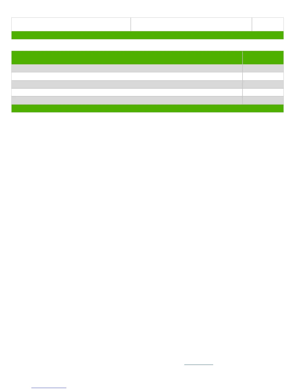
List the type and size of the tools that would typically be used to disassemble the product to a point where components
and materials requiring selective treatment can be removed.
Tool Size (if
applicable)
Description #1 Screw driver
Description #2 Screw driver
Description #3 Screw driver
Description #4 Screw driver
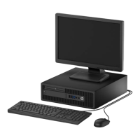
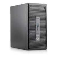
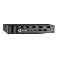
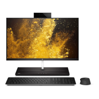
3.0 Product Disassembly Process
3.1 List the basic steps that should typically be followed to remove components and materials requiring selective treatment:
1. [system parts] Remove the stand
2. [system] Remove TOP bezel
3. [System] remove memory FAN
4. [System] Remove the HDD
5. [System] Remove Cpu thermal module
6. [System]Remove ODD
7. [System]Remove site IO board
8. [System] Remove rear IO board
9. [System]Remove EMI CAN
10. [System]Remove speaker
11. [System] Remove MXM power connector
12. [System] Remove PSU
13. [System] Remove hinge& panel IO cable
14. [System]Remover antenna
15. [System] Remove MXM module
16. [System] remove PCIE card
17. [System] Remove MB
18. [System] Remove CPU bracket/CPU
19. [System] Remove memory
20. [System] remove spring
21. [System]Remove front bezel
22. [System]Remove web camera module
23. [System]remove latch
24. [System]remove touch plan
25. System]PSU
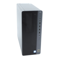
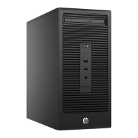
3.2 Optional Graphic. If the disassembly process is complex, insert a graphic illustration below to identify the items
contained in the product that require selective treatment (with descriptions and arrows identifying locations).
EL-MF877-00 Page 2
Template Revision B
PSG instructions for this template are available at EL-MF877-01
 Loading...