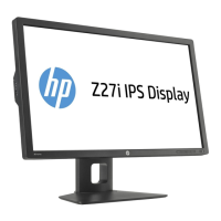
3.0 Product Disassembly Process
3.1 List the basic steps that should typically be followed to remove components and materials requiring selective treatment:
1. Use tool to separate head and stand.
2. Use tool to release screws and disassemble the rear cover by hand.
3. Separate rubber and RC by hand.
4. Tear AL-tape and acrylic adhesive tape off and separate FFC wire from connecter.
5. Remove USB SHD and use tool to release screw.--> Separate USB BD from Main Chassis.
6. Take the lamp wire off from panel and use tool to release side mount screws.
7. Use tool to release screws on PCBs. Then tear down the gaskets, rubber and AL tapes on main chassis and separate
all connector on PCBs.
8. Use tool to release screws on CTRL BD and take Ctrl BD off from assy-BZL.
9. Use tool to separate OSD-BTN and PWR-BTN parts from BZL. And use pin at back side to separate the logo.
10. Use tool to release screws and separate VESA BKT from stand.
11. Separate cable clip from stand by hand.
12. Separate Lift front CVR from stand by hand and use tool to release screws --> separate Lift back CVR from stand.
13. Use tool to release screws --> separate tilt CVR from stand.
14. Separate Clum front CVR from stand by hand and use tool to release screws --> separate Clum back CVR from stand.
15. Tear all rubbers and release screws on base.
16. There are capacitors on Interface BD , PWR BD and USB BD
3.2 Optional Graphic. If the disassembly process is complex, insert a graphic illustration below to identify the items
contained in the product that require selective treatment (with descriptions and arrows identifying locations).

 Loading...