TL-LFP Series liFePO
4
Battery Operation Manual
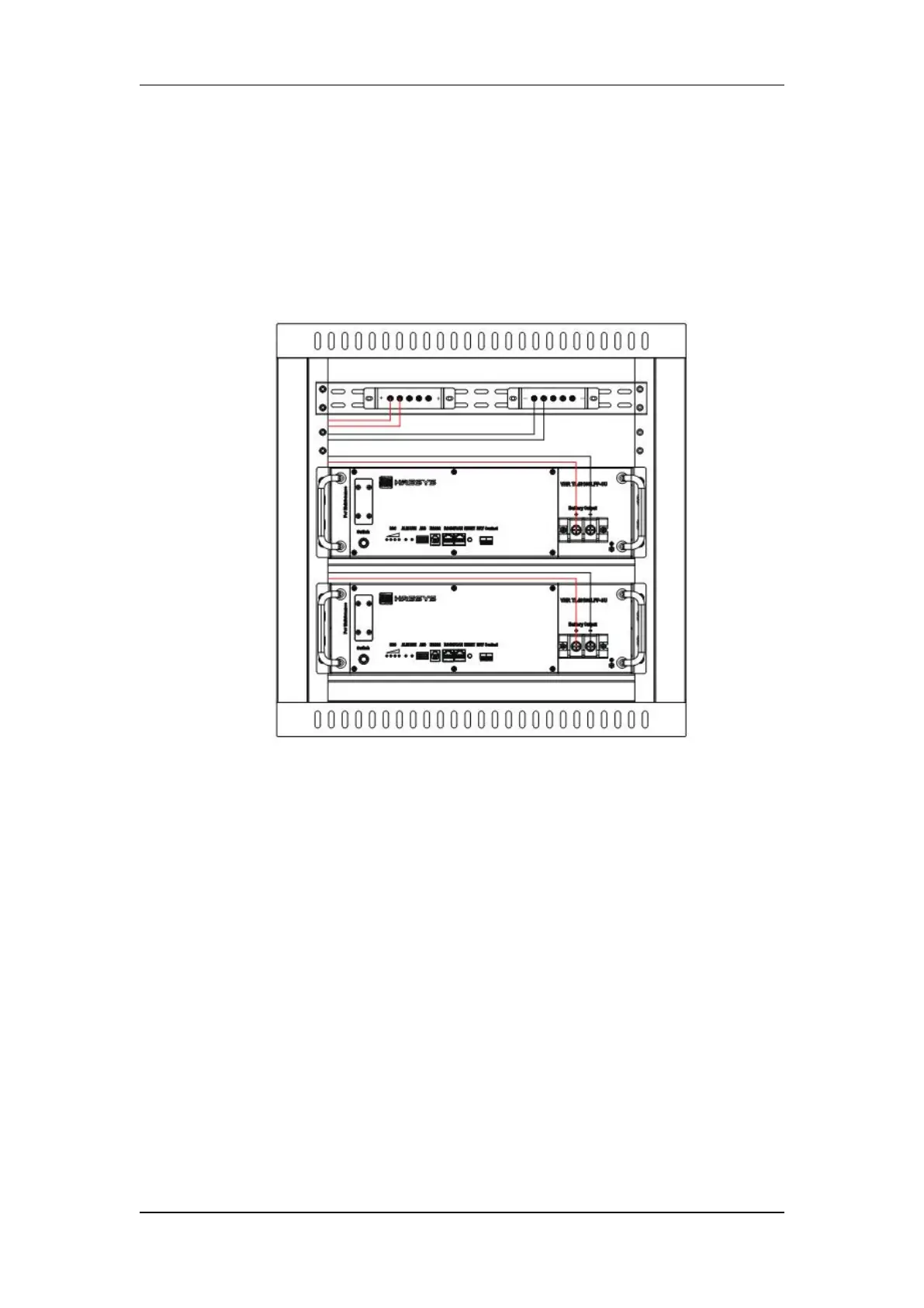
copper bus bar separately.
Length of cable between battery module and power plant shall be less than 2.0m. To
make sure similar voltage drop of cable for each battery, length of all positive and
negative cables should be the same.
Color for cable between
‘
+
’
and positive female bar is suggested as red, and cable
between ‘-’ and negative breaker or fuse as black.
4) Power on for battery module
When installation is accomplished, firstly turn on the battery switch and the LED
indicator will light up, then close the circuit breaker of the rectifier to power on. Once
power on for power plant, battery module will go into normal running status, and
discharge/charge can be available.
Parameter settings for lithium battery modules in power plant are shown in Table 4.2.
5) RS232/RS485 connection
If there is only one battery module in operation, communication between battery
module and upper computer can available through both RS232 and RS485.
If there are more than one battery modules in operation, parallel communication can
be available using RS485.
Communication protocols for RS232 and RS485 are shown in Annex 3.
6) Discharge with dummy load
Dummy load cannot be larger maximum discharge current of each battery model in
 Loading...