The HRESYS TL-LFP Series Lithium-ion Battery is a sophisticated power solution designed for various indoor and outdoor applications, including telecommunication, FTTX terminals, access network systems, indoor distribution systems, integrated outdoor power cabinets, internet data centers (IDC), and energy storage systems. This battery series leverages advanced LiFePO4 technology and an intelligent integrated Battery Management System (BMS) to offer a long cycle life, light weight, compact size, and enhanced safety and environmental protection.
Function Description:
The TL-LFP series battery system operates as a communication standby power supply, comprising several lithium iron phosphate battery units connected in series with a dedicated high-performance and high-reliability BMS. The battery's output terminals connect to the rectifier's terminals. Under normal mains supply, telecommunication equipment is powered by rectified mains power, and the battery pack is charged. In the event of a mains power interruption, the battery provides immediate backup power to the telecommunication equipment, ensuring uninterrupted operation until mains power is restored or the BMS initiates overdischarge protection.
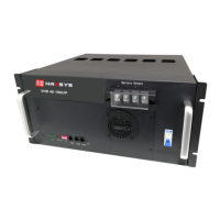
The BMS is central to the battery's operation, performing critical functions such as overcharge/overdischarge voltage detection, over-current/short-circuit detection, and temperature detection. It also controls the output MOS switch and communicates with the power plant via RS232 and RS485 protocols. The front panel features an LCD screen (optional) that displays current system total voltage, current, and battery status, along with various indicators for State of Charge (SOC), alarms (ALM), and running status (RUN). An ON/OFF switch allows the battery to enter sleep mode and cut off output, simultaneously stopping alarm output. The ADD dialing feature enables parallel connection of up to 64 battery modules, with each module assigned a unique binary address.
Important Technical Specifications:
- Battery Type: LiFePO4
- Rated Voltage: 48V
- Operating Temperature Range:
- Discharge: -20°C to +60°C
- Charge: 0°C to +60°C
- Storage: 0°C to +40°C
- Recommended Temperature Range:
- Discharge: +15°C to +35°C
- Charge: +15°C to +35°C
- Storage: +15°C to +30°C
- Humidity: 5% to 95%
- Power Plant Parameter Settings (for TL48V-LFP Series Batteries):
- Float voltage charge: 54V
- Equal voltage charge: NA or 54V (Equalization charge should be switched off for TL-LFP series battery)
- Standard charge current: 0.2C
- Charge current limitation: 0.5C ~ 1.0C
- LVLD (Low voltage load disconnection): >44V
- LVBD (Low voltage battery disconnection): >41V
- Temperature compensation for float charge: NA
- Temperature compensation for equalization charge: NA
- System instantaneous discharge and charge current: Less than 250A per module.
- Charge Modes and Conditions (based on Cell Temperature):
- <0°C: No Charge Allowed
- 0°C~10°C: Recommended Charge Current: 0.1C, Fast Continuous Charge Current: 0.2C
- 10°C~20°C: Recommended Charge Current: 0.2C, Fast Continuous Charge Current: 0.5C
- 20°C~30°C: Recommended Charge Current: 0.3C, Fast Continuous Charge Current: 1.0C
- 30°C~40°C: Recommended Charge Current: 0.3C, Fast Continuous Charge Current: 1.0C
- 40°C~60°C: Recommended Charge Current: 0.3C, Fast Continuous Charge Current: 0.5C
-
60°C: No Charge Allowed
- Discharge Modes and Conditions (based on Cell Temperature):
- <-20°C: No Discharge Allowed
- -20°C~0°C: Recommended Discharge Current: 0.2C, Fast Discharge Current: 0.5C
- 0°C~20°C: Recommended Discharge Current: 0.5C, Fast Discharge Current: 1.0C
- 20°C~50°C: Recommended Discharge Current: 0.5C, Fast Discharge Current: 1.0C
- 50~60°C: Recommended Discharge Current: 0.2C, Fast Discharge Current: 0.5C
-
60°C: No Discharge Allowed
- Recharge Parameters:
- Charge voltage: 54.0V
- Charge current: Default charge current limit, typically ≤ 0.2C
- Termination condition: Charge duration > 10 minutes and charge current < 0.03C, or BMS protection activated.
- Communication Ports:
- RS232 (RJ11, 6-pin): For up-link communication with upper computer (Master PACK only, address 000000).
- RS485 (RJ45, 8-pin): For cascading communication with parallel-connected battery modules (Slave PACKs).
Usage Features:
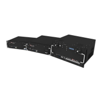
- Installation Flexibility: Battery modules are designed for installation in 19-inch cabinets or wall-hanging configurations. For cabinet installation, modules are secured with M6 screws; for wall-hanging, they are fixed to a triangle rack with M6 screws.
- Ground Connection: A GND screw on the front panel allows for grounding with a flexible cable no less than 6AWG.
- Battery Output Connection: Before connecting power cables, the rectifier's circuit breaker must be open. Positive terminals connect to the positive copper bus bar of the power plant, and negative terminals to the negative copper bus bar. For parallel connections, each module's positive and negative outputs connect to the respective bus bars. Cable length between the battery module and power plant should be less than 2.0m, with all positive and negative cables being of equal length to ensure similar voltage drop. Red is suggested for positive cables, black for negative.
- Power-on Sequence: After installation, turn on the battery switch first, then close the rectifier's circuit breaker. The LED indicators will light up, and the battery module will enter normal running status, enabling discharge/charge.
- Communication: A single battery module can communicate with an upper computer via both RS232 and RS485. For multiple parallel-connected modules, RS485 is used for communication between modules and with the Master PACK.
- SOC Indicators: Four green LED lights on the front panel indicate the State of Charge, with each light representing 25% of the rated capacity.
- Alarm and Run Indicators: A red LED indicates alarms, and a green LED indicates running status.
- RESET Button: Allows for resetting the battery in case of abnormality to ensure stable performance.
- DRY CONTACT (Optional): A signal interface typically triggered by alarms or protection events.
- Storage Guidelines: Modules should be stored in cartons with 20%-50% capacity, avoiding violent vibration, impact, squeezing, direct sunlight, or rain. Storage environment should be dry, clean, well-ventilated, free from corrosive/organic substances, direct sunlight, and heat sources (at least 2 meters away).
- Recharge Process for Overdue Storage: Modules stored for extended periods (12 months for 0℃≤T≤30°C, 8 months for 30℃≤T≤40℃) require recharging. The process involves connecting the module to a DC regulated power supply, setting the charge voltage to 54.0V, and using a charge current typically ≤ 0.2C until the charge duration is greater than 10 minutes and the charge current is less than 0.03C, or the BMS is protected.
Maintenance Features:
- Professional Installation and Maintenance: Installation must be performed by professional training staff, and maintenance by experienced professionals aware of potential hazards.
- Safety Precautions: During operation, remove watches, rings, or other metal objects. Use tools with insulated handles and avoid placing tools or metal objects on the battery. Do not connect the battery system directly to the mains grid, expose it to fire, or store it near high-temperature sources. Avoid placing liquid or other objects into the battery system, and do not open, cut, hit, throw, or step on the battery.
- Regular Cleaning: Dust accumulation on vents should be cleaned with a dust collector. The cabinet should be cleaned with a clean, dry cloth/fabric; neutral cleanser can be used if needed, but alcohol or ammonia synthesis is forbidden.
- Physical Handling: Handle the battery gently to prevent severe impact. Prevent liquid from splashing onto the battery.
- Output Screw Inspection: It is suggested to inspect the tightness of output screws every two years.
- Troubleshooting Guide: The manual provides a comprehensive troubleshooting table for common issues such as battery discharge/charge failure, failure to start, LED indicator problems, and communication failure, along with corresponding solutions.
- Storage Monitoring: Warehouse keepers should monthly collect and report storage information. Modules stored overdue must be recharged promptly.
- Warranty and Degradation: Bulging modules should be handled directly. Battery performance degradation after long-term storage may necessitate shortening shelf time.