TL-LFP Series liFePO
4
Battery Operation Manual
4.4 – Layout of Front Panel
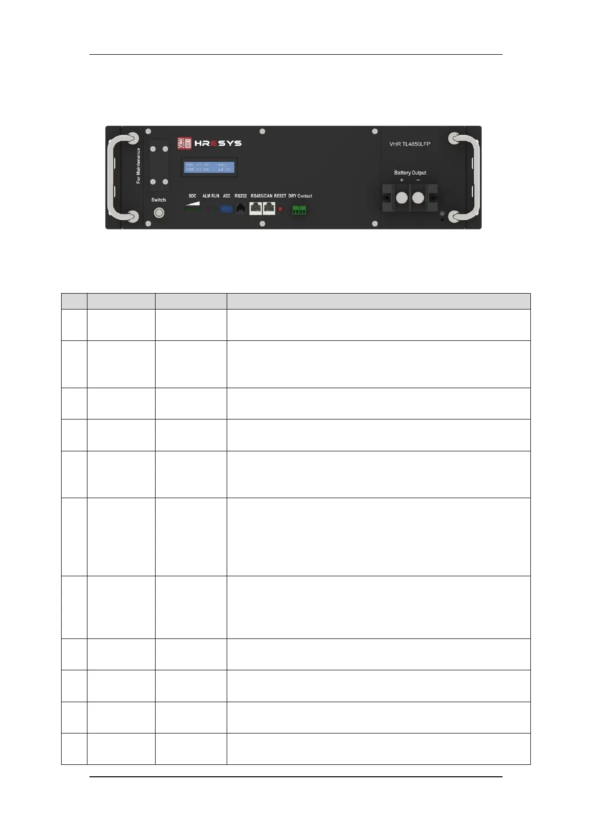
Fig. 4.1
–
Layout of Front Panel for TL-LFP Series Batteries
Table 4.5 – Instruction for Layout of Front Panel
When turn-off, battery get into sleep mode, and cut-off output, the alarm
output also will be stopped.
There are four green LED lights in front panel indicating SOC.SOC is short for
state of charge. Each SOC LED light represents 25% of rated capacity. Detailed
information is shown in Annexed Table 1.1.
There is one red LED light in front panel indicating alarms. Detailed information
is shown in Annexed Table 1.2.
Indicator for
running status
There is one green LED light in front panel indicating running status. Detailed
information is shown in Annexed Table 1.2.
ADD is applicable to modules connected in parallel. ADD consists of four binary
bits, and maximum quantity of batteries connected in parallel is 64pcs (2^6).
Detailed information is shown in Annex 2.
It is adopting RS-232 series port to upload data. Contents of data transmit
include BMS parameters, battery running status, alarms, etc.Generally, speed
rate of RS-232 is 1200bps. RS232 up-link communication can be available for the
battery module with a binary communication address of 0000 (Master PACK).
Protocol for RS232 communication is shown in Annexed Table 3.1
Cascading
communication
port
It is adopting RS485 series port communication pattern to upload data.
Communication of modules connected in parallel (Slave PACKs) is available
through RS 485. Data of slave PACKs will be transmitted to Master PACK.
Protocol for RS232 communication is shown in Annexed Table 3.2
Press RESET button when abnormity occurs to assure stability of battery
performance.
It is usually triggered by alarm or protection
Terminals for
battery output
Using terminals with two or four cores. Polarities are +, -, +, - from left to right.
The two
‘
+
’
and
‘
-
’
are equal relatively.
 Loading...