Do you have a question about the HT PV-ISOTEST and is the answer not in the manual?
Crucial safety recommendations to follow while operating the instrument.
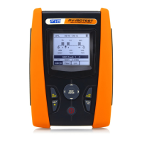
Details the primary capabilities and features of the PV-ISOTEST.
How to configure system parameters like language and date/time.
Procedure for testing protective conductor continuity on PV systems.
How to perform continuity measurements in Standard mode.
How to perform continuity measurements using the Timer mode.
Procedure for measuring insulation resistance on PV systems.
Performing insulation tests between poles and earth in DUAL mode.
Performing insulation tests with timed measurements.
Function to locate low insulation faults in PV strings.
Using the instrument as a multimeter to measure voltages.
How to save measurement results and add markers or comments.
Specific electrical and performance data of the instrument.
| DC Voltage Test Range | 0 - 1000 V |
|---|---|
| Insulation Resistance Test Voltage | 250 V, 500 V, 1000 V |
| Display | LCD |
| Continuity Test | Yes |
| PV String Test | Yes |
| Data Logging | Yes |
| PC Interface | USB |
| Power Supply | 6x 1.5V AA batteries |
| Weight | 1.2 kg |