Do you have a question about the HT FULLTEST3 and is the answer not in the manual?
Safety guidelines and precautions before operating the instrument.
Safe operating procedures and warnings while using the instrument.
Instructions for safely switching off and disconnecting the instrument.
Explanation of IEC/EN61010-1 measurement categories for electrical equipment.
Overview of the instrument's primary functions and capabilities.
Step-by-step guide on how to safely open the instrument's protective cover.
Mechanical and electrical checks to ensure the instrument is in perfect condition before use.
Requirements for connecting the instrument to a grounded power supply for safe operation.
Guidelines for storing the instrument to ensure measurement precision.
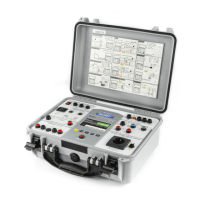
Detailed description and identification of all parts and connectors of the instrument.
Procedure for powering on the instrument and initial startup sequence.
How to navigate and select different measurement functions available on the instrument.
Managing saved measurement results, including viewing, clearing, and transferring data.
Defining operator names for inclusion in final reports transferred to PC.
Selecting the desired language for the instrument's interface.
Displaying essential tester information such as firmware and serial numbers.
Configuring instrument parameters like date/time, voltage, and safety settings.
Resetting adjustable parameters to factory default values without deleting memory data.
Configuring the safety level status for DIELECTRIC function according to EN50191.
Enabling or disabling the acoustic signals (beeps) for instrument feedback.
Defining and executing custom test groups (Autotests) for rapid, repetitive testing.
Performing continuity tests of the protective conductor using the 2-wire method.
Calibrating test leads to ensure accurate measurements by zeroing lead resistance.
Setting reference limits for continuity tests performed with 25A current, based on conductor or line impedance.
Identifying and interpreting specific error messages or conditions during PE conductor continuity tests.
Performing continuity tests of the protective conductor using the 4-wire Kelvin method.
Setting reference limits for continuity tests based on conductor length or line impedance.
Identifying and interpreting error messages during 4-wire continuity tests.
Measuring insulation resistance between machine power circuits and earth using 500VDC.
Identifying and interpreting messages related to external voltage or discharging during insulation tests.
Performing high voltage tests to verify insulation strength between conductors and earth.
Explanation of different operating modes for dielectric tests (Manual, Burn, Pulse, Ramp).
Measuring dielectric leakage current using IAPP (total RMS) or IREAL (real part) modes.
Configuring and using safety input and warning lamps for high voltage dielectric tests.
Identifying and interpreting error messages during dielectric tests, such as internal fuse errors.
Measuring time and trip-out current for various RCD types and characteristics.
Identifying and interpreting error messages during RCD tests, like voltage range or contact voltage issues.
Measuring fault loop impedance and calculating prospective short-circuit current.
Selecting modes for verifying protection device reaction against short-circuit currents.
Calculating short-circuit current based on system parameters and protection device characteristics.
Identifying and interpreting error messages during loop impedance tests, such as voltage out of range.
Measuring global earth resistance and contact voltage, especially in TT systems.
Setting limit values for global earth resistance based on contact voltage and nominal trip-out current.
Identifying and interpreting error messages during earth resistance tests.
Measuring residual voltage on machine parts after power disconnection to ensure safety.
Measuring residual voltage in linear mode, considering exponential discharge characteristics.
Measuring residual voltage in non-linear mode, where discharge is unpredictable.
How the instrument detects voltage changes to start residual voltage measurements.
Identifying and interpreting messages like low trigger voltage during residual voltage tests.
Performing functional tests to measure voltage, current, and power parameters of connected equipment.
Identifying and interpreting overrange messages for leakage or load current during power tests.
Testing the phase sequence in a three-phase system using a 3-wire method.
Identifying and interpreting voltage out of range messages during phase sequence tests.
Measuring AC current using a transducer clamp connected to the instrument.
Identifying and interpreting current overrange messages during clamp current measurements.
Measuring AC leakage current using a transducer clamp or directly via the test socket.
Identifying and interpreting overrange messages for leakage current during socket tests.
Executing predefined Autotest sequences for automated testing procedures.
Procedures for saving measurement results to the instrument's internal memory with level and comment details.
Saving completed Autotest sequences for later recall or execution.
Retrieving and displaying previously saved measurement results from the instrument's memory.
Using a USB keyboard for simplified data entry into the instrument's memory.
Using a USB barcode reader for efficiently entering customer data into memory.
Initial configuration steps for a Honeywell Voyager barcode reader.
General recommendations for instrument use, storage, and handling to prevent damage.
Guidelines for safely cleaning the instrument using appropriate methods.
Procedures for replacing internal fuses (F1, F2, F3, F4) by qualified technicians.
Information regarding the disposal of the equipment and accessories at the end of their service life.
Technical specifications for RPE-2WIRE (200mA/25A) and RPE-4WIRE (25A) continuity tests.
Technical specifications for Insulation Resistance (ΜΩ) and Dielectric Withstanding Tests.
Technical specifications for RCD, Loop Impedance, and Global Earth Resistance tests.
Technical specifications for Residual Voltage, Power, Phase Sequence, and Leakage Current tests.
Technical specifications for ICLAMP and ILEAK current measurements using transducer clamps.
| Brand | HT |
|---|---|
| Model | FULLTEST3 |
| Category | Test Equipment |
| Language | English |