FULLTEST3
EN - 27
6. OPERATIVE INSTRUCTIONS
6.1. CONTINUITY OF PE CONDUCTOR – 2-WIRE METHOD (RPE-2WIRE)
Complying with IEC/EN60204-1 the continuity of protective bonding circuit between
PE terminal and relevant points of the protective conductor system must be checked
by injecting a measurement current of 0.2 A up to 10 A approx. The instrument allows
to perform the test with 200mA and 25A test current (for resistance between
terminals <0.1:) or 10A (for resistance between terminals <0.5:) with automatic
recognition.
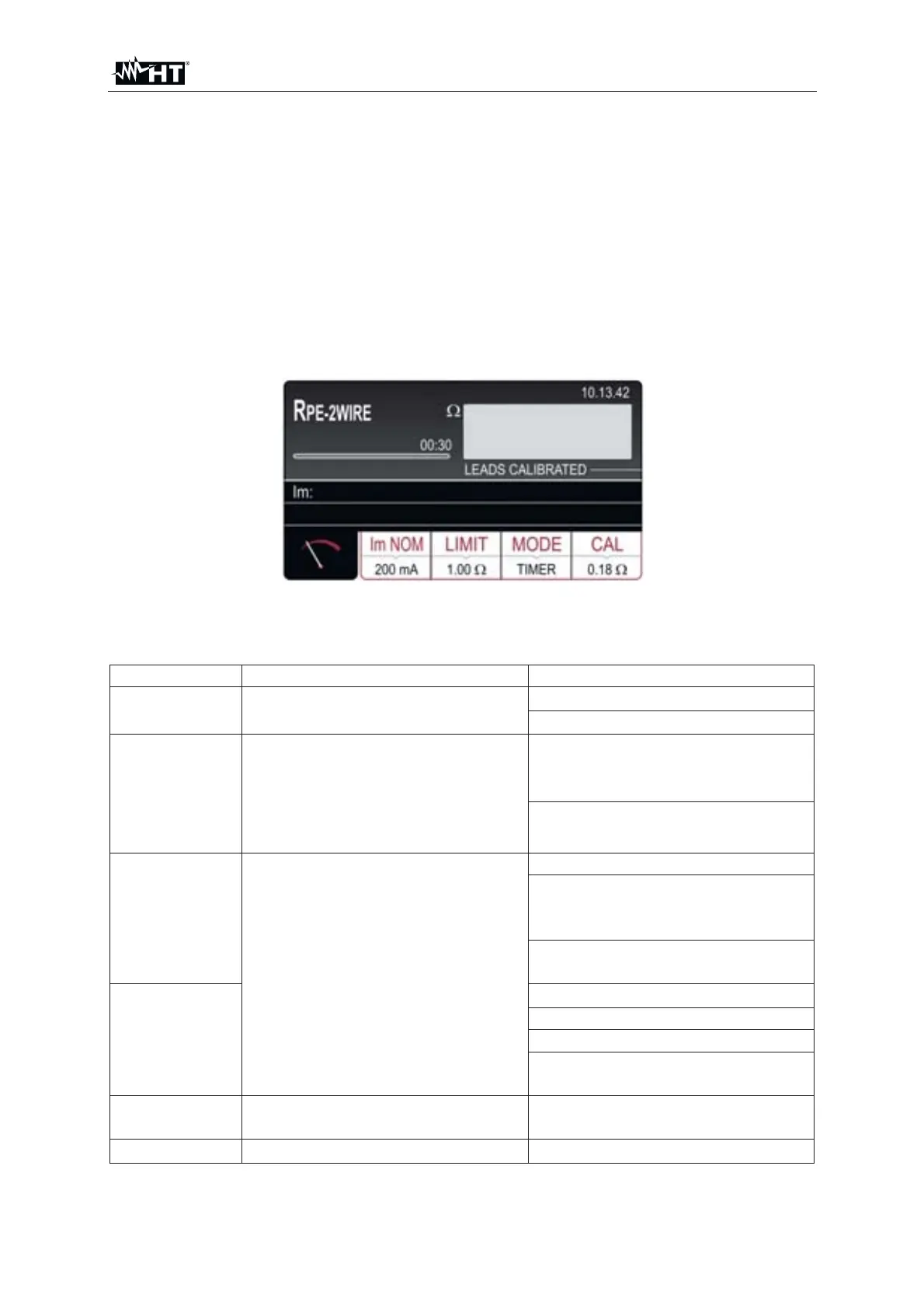
1. Press the FUNC key and select the RPE-2WIRE function. The following screen is
shown on the display
Fig. 25 : RPE-2WIRE initial screen
2. Select the test parameters on the instrument (see Table 1) and carry out the
desired setup
Parameter Description Value
Im NOM Nominal test current
200mA or 25A AC (R<0.1:)
200mA or 10A AC (R<0.5:)
LIMIT Reference limit threshold
STANDARD
0.01: ÷ 200.0: (200mA)
0.01: ÷ 20.0: (25A)
60204 SET L (25A)
60204 SET Z (25A)
60204 SET L
Test with 25A current
(see § 6.1.2)
Length: 0.1m ÷ 999.9m
Section: 1, 1.5, 2.5, 4, 6, 10, 16,
25, 35, 50, 70, 95, 120, 150, 185,
240, 300, 400, 500, 630 mm
2
Material: Cu (Copper) or Al
(Aluminum)
60204 SET Z
ZLine: 0.001: y 2.000:
MCB protection: B, C, D, K
Fuse protection: gG, aM
Nominal current protection
(see §)
MODE Measurement mode
Manual
Timer (2s ÷ 60min)
CAL
Test leads calibration
up to 5.00:
Table 1 : Setup parameters of RPE-2WIRE function