FULLTEST3
EN - 61
6.8. RESIDUAL VOLTAGE (U
RES)
Residual voltage means the voltage that remains on accessible parts of a machine
after it has been turned off. This phenomenon can be caused for example by
integrated capacities or internal generators and must be kept within appropriate
values for operator safety reasons. In accordance with the requirements of IEC/
EN60204-1 guideline, accessible live parts connected to dangerous voltages must
discharge within 5s (machines permanently powered) or within 1s (machines
connected with plugs, terminal blocks, drives, etc. ) up to 60V. This must be verified
by means of appropriate evaluation tests of the discharge time. In the event of non-
compliance, additional measures must be taken (discharge devices, warning
information, covers, etc.). The residual voltage must be measured 1s or 5s after
turning off the tested machine. The instrument can perform the URES measurement
in the following modes:
¾ Linear mode on plug-in machines (Plug)
¾ Linear mode on permanently connected machines (Internal)
¾ Non-Linear mode on plug-in machines (Plug)
¾ Non-Linear mode on permanently connected machines (Internal)
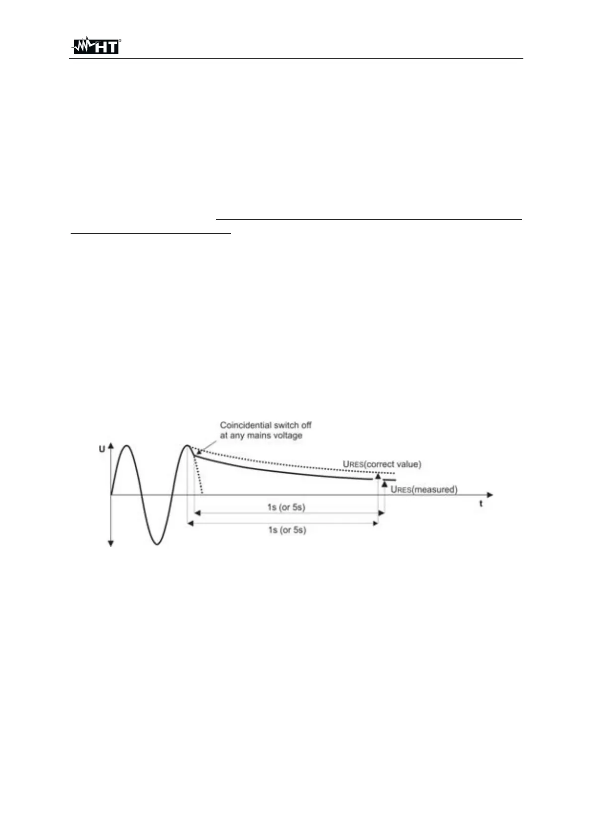
6.8.1. Linear mode
In Linear mode it is considered that the internal components of the machine are
exclusively "linear" (resistances, inductances, capacitances, etc.) therefore the
discharge characteristic of the supply voltage is typically inverse exponential. In this
way the displayed result refers to the peak value of the supply voltage so as to
evaluate the most critical situation (see
Fig. 55 : Discharge supply voltage in linear mode
In order to calculate the measured URES voltage it is necessary to know the nominal
value of the supply voltage Un Phase-Neutral or Phase-Earth therefore it is
necessary to select it on the instrument before performing the measurements (see §
5.5). The instrument automatically detects the below standard system voltages (e.g.
230V/240V)
¾ Nominal voltage selected Un = 230V
230V Æ U
IN = 230V r 10%
400V Æ U
IN = 400V r 10%
¾ Nominal voltage selected Un = 240V
240V Æ U
IN = 240V r 10%
415V Æ U
IN = 415V r 10%
In order to include standard mains over-voltage, the measured residual voltage is
scaled to peak value of max. possible mains over-voltage, i.e.: