FULLTEST3
EN - 37
6.3. INSULATION RESISTANCE (M
)
In accordance with the requirements of the IEC/EN60204-1 guideline, the insulation
resistance between the machine power circuits and the earth reference must be
checked by applying a test voltage of 500VDC. The minimum reference limit value is
1M
. Make sure that all the switches of the object under examination are closed in
order to check all its components. For the measurement, all active conductors (L1,
L2, L3 and N) must be short-circuited. Disconnect or dissect all machine control
parts/logics that could be damaged by the test voltage
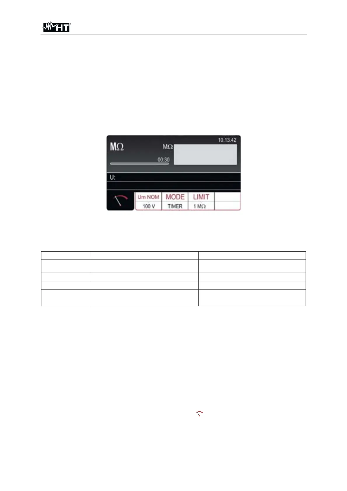
1. Press the FUNC key and select the M
function. The following screen is shown
on the display
Fig. 32 : M: initial screen
2. Select the test parameters on the instrument (see Table 3) and carry out the
desired setup
Parameter Description Value
Um NOM Nominal test voltage 100, 250, 500, 1000VDC
MODE Measurement mode Manual, Timer, Auto
TIMER Measurement time 00:01 ÷ 60:00 (1s ÷ 60min)
LIMIT
Minimum reference limit
threshold
0.01M: ÷ 100.0M:
Table 3 : Setup parameters of RPE-4WIRE function
3. Check selected mode and modify it if needed by pressing the MODE touch-
screen key first. MANUAL, TIMER or AUTO mode can be selected. In MANUAL
mode, the measurement is activated/terminated by pressing the START/STOP
key. In TIMER mode, the measurement is activated by pressing the
START/STOP key and is finished or upon reaching a stable result at the end of
the set measurement time or by pressing the START/STOP key again. In AUTO
mode the measurement is finished when a stable result is reached
4. Check selected limit value and modify it if needed by pressing the LIMIT touch-
screen key first. Four independent preset limit values are available for quicker
operations. Select the one closest to wished value and modify it by using the +
and ʊ touch screen keys if needed
5. Select measurement screen by pressing the
touch-screen key and check all
settings again
6. Connect the test leads according to the below Fig. 33