FULLTEST3
EN - 38
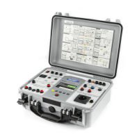
Fig. 33 : Connection of test leads in M: function
7. Press the START/STOP key to perform the measurement. The test result is
shown on the display (see Fig. 34)
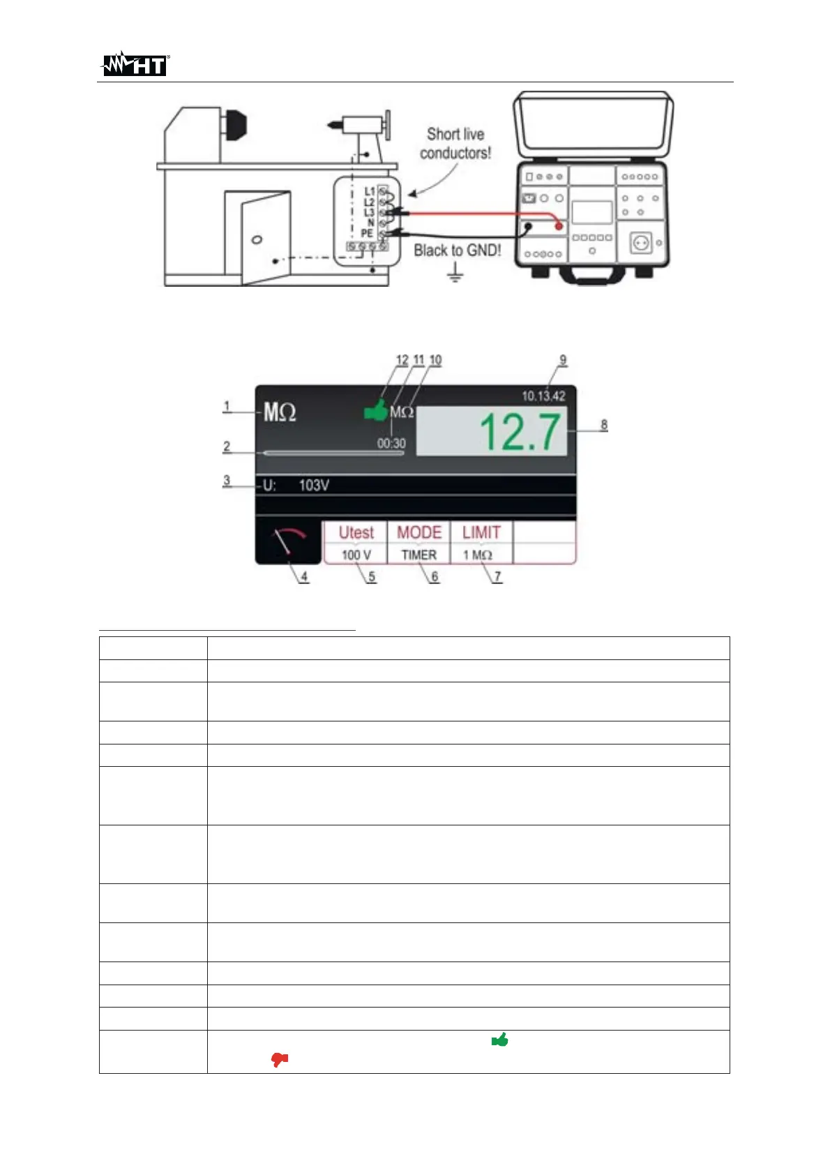
Fig. 34 : Visualization of M: test result
Meaning of symbols on the display
Item Description
1 Selected function
2
Progress bar, it follows measurement time during the measurement
(in TIMER mode only)
3 Test voltage applied during the measurement
4 Measurement screen touch-screen key
5
Utest touch-screen key to select nominal test voltage (100, 250, 500
or 1000VDC). Currently selected value is displayed on the bottom of
the key
6
MODE touch-screen key to select operation mode (MANUAL, TIMER
or AUTO). Currently selected mode is displayed on the bottom of the
key
7
LIMIT touch-screen key to select limit insulation resistance. Currently
selected value is displayed on the bottom of the key
8
Measurement value (in green color - result OK, in red color - result
NON OK
9 Real time clock (hh.mm.ss).
10
Unit of measurement result (M:)
11 Set measurement time (in TIMER mode only)
12
Measurement result status (symbol
in green color - result OK,
symbol
in red color – result not OK)