FULLTEST3
EN - 46
6.5. TEST ON RCD (RCD)
The instrument allows measurement of time and trip out current (Ramp) on RCD’s
protection devices type A, AC and B, General, Selective and Delayed according to
the IEC/EN61008 and IEC/EN61009 reference guidelines.
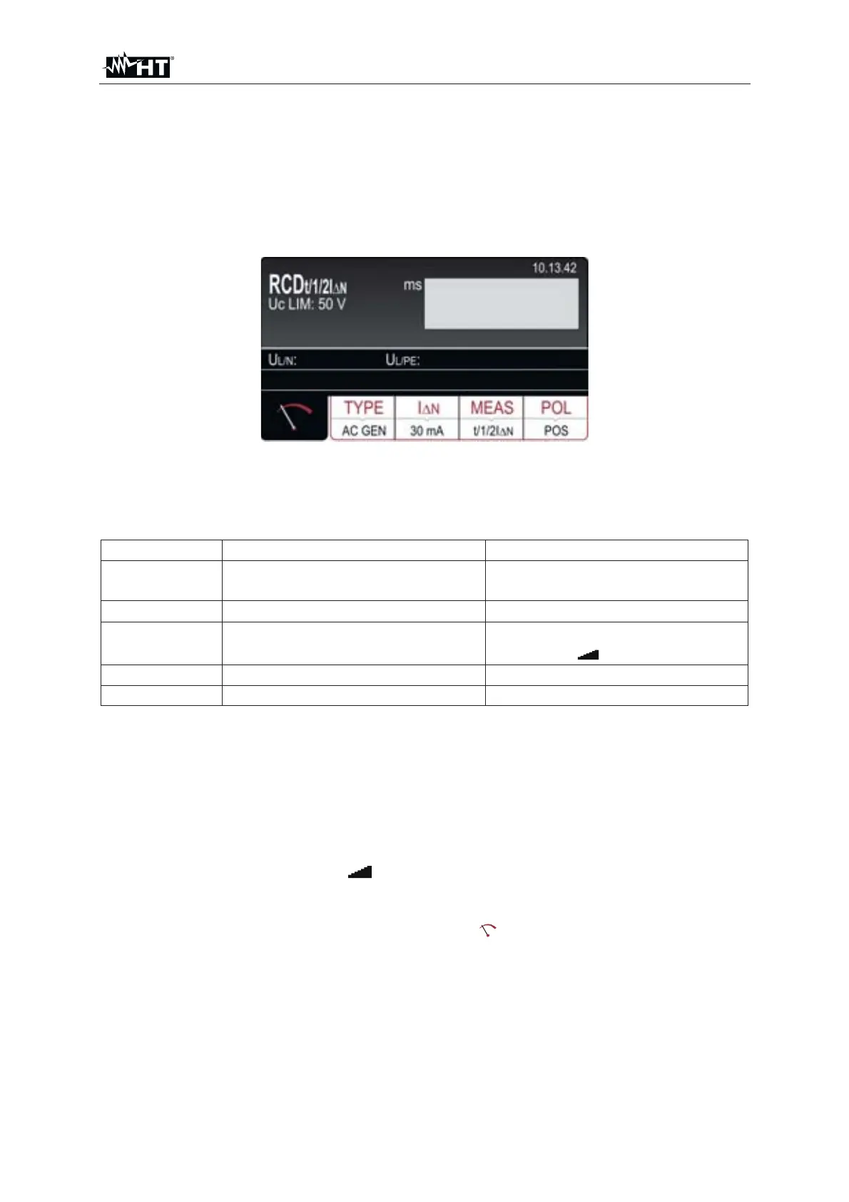
1. Press the FUNC key and select the RCD function. The following screen is shown
on the display
Fig. 41 : RCD initial screen
2. Select the test parameters on the instrument (see Table 5) and carry out the
desired setup
Parameter Description Value
TYPE RCD typology
AC, A, B
General, Selective, Delayed
I'N
Nominal trip out current of RCD 10,30,100,300,500,650,1000mA
MEAS
Measurement modes
(trip out time and current)
t/½I'N, t/I'N, t/2I'N, t/5I'N,
I'
or AUTO
POL Test current polarity Positive (0°), Negative (180°)
T DEL Delayed time (for delayed RCD) 0ms ÷ 700ms
Table 5 : Setup parameters of RCD function
3. Check selected RCD type (AC, A or B) and selected characteristic (GENERAL,
SELECTIVE or DELAYED) and modify it if needed by pressing the TYPE touch-
screen key first. If DELAYED characteristic is selected, the screen will turn to
delay time adjustment mode automatically
4. Select nominal differential current by pressing the I
N touch-screen key first
5. Select wished measurement by pressing the MEAS touch-screen key first
(t
/1/2I'N, t/I'N, t/2I'N, t/5I'N, I' or AUTO)
6. Check selected polarity and modify it if needed by pressing the POL (8) touch-
screen key first
7. Select measurement screen by pressing the
touch-screen key and check all
settings again
8. Connect the test leads or te schuko cable as shown in the followed Fig. 42 or Fig.
43