FULLTEST3
EN - 34
6.2.1. Set limit value
The instrument allows to perform the continuity test by calculating the reference limit
as a function of the length (known in advance) of the conductor or as a function of the
impedance of the line power source in accordance with the requirements of the
IEC/EN60204-1 guideline.
EN60204 SET L mode
The limit value is calculated based on the length, section and material of the
conductor under test. The parameters can be selected/adjusted within the values
shown in Table 1
EN60204 SET Z mode
The limit value is calculated based on the input line impedance (ZLINE), the type of
protection of the line, the rated current of the protection and the section of the
conductor under test. The values of the selectable parameters are the followed:
¾ Line impedance range: 0.001
÷ 2.000
in steps of 0.001:
¾ Type of MCB protection: B, C, D, K curves
¾ Nominal current of MCB protection: 6, 10, 13, 16, 20, 25, 32, 40, 50, 63A (B
curve), 0.5, 1, 1.6, 2, 4, 6, 10, 13, 16, 20, 25, 32, 40, 50, 63A (C curve), 0.5, 1,
1.6, 2, 4, 6, 10, 13, 16, 20, 25, 32A (D, K curves)
¾ Type of Fuse protection: gG, aM
¾ Nominal current of Fuse protection gG: 2, 4, 6, 10, 13, 16, 20, 25, 32, 35, 40, 50,
63, 80, 100, 125, 160, 200, 224, 250, 315, 355, 400, 500, 630A
¾ Nominal current of Fuse protection aM: 6, 10, 16, 20, 25, 32, 35, 40, 50, 63, 80,
100, 160, 224, 250, 315, 355, 400, 500, 630A
¾ Conductor section: 1, 2.5, 4, 6, 10, 16, 25, 35, 50, 70, 95, 120, 150, 185, 240,
300, 400, 500, 630mm
2
3. Check selected mode (MANUAL or TIMER) and modify it if needed by pressing
the MODE key. In MANUAL mode the measurement will start after pressing the
START/STOP key and will stop after pressing the START/STOP key again. In
TIMER mode the measurement will start after pressing the START/STOP key and
will stop after elapsing set measurement time or after pressing the START/STOP
button again
4. Select measurement screen by pressing the
touch-screen key and check all
settings again
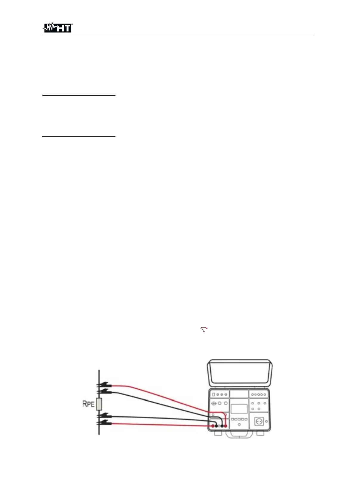
5. Connect the test leads according to the below Fig. 30
Fig. 30 : Connection of test leads in R
PE-4WIRE function