FULLTEST3
EN - 30
CAUTION
Before connecting test leads to UUT obligatory assure there is
no external voltage higher than 10 V between the test points
where test leads will be connected to, otherwise fuse F4 may
blow
10. Press the START/STOP key to perform the measurement. The test result is
shown on the display (see Fig. 28)
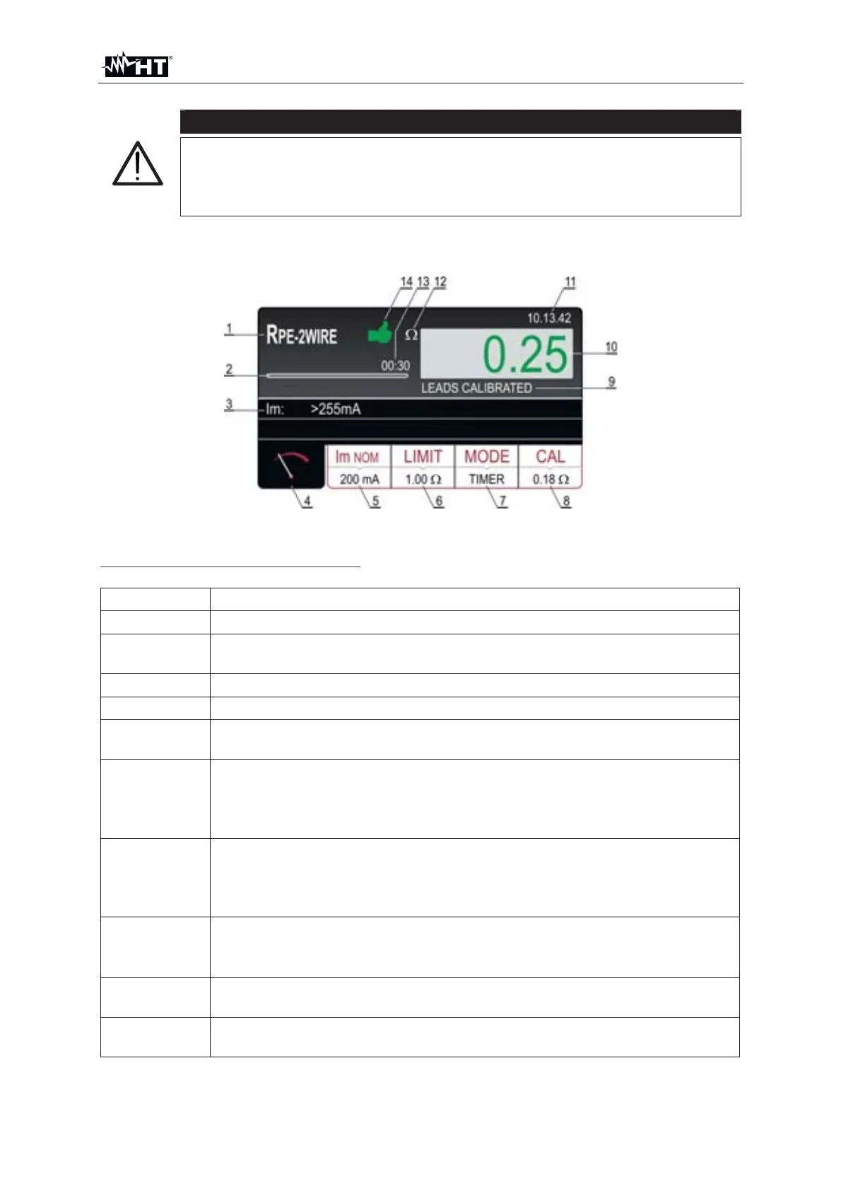
Fig. 28 : Visualization of R
PE-2WIRE test result
Meaning of symbols on the display
Item Description
1 Selected function
2
Progress bar, it follows measurement time during the measurement
(in TIMER mode only)
3 Sub-result – real test current applied
4 Measurement screen touch-screen key
5
Im
NOM touch-screen key to select nominal test current (200 mA or
25 A). Currently selected value is displayed on the bottom of the key
6
LIMIT touch-screen key to select limit value (200 mA measurement)
or limit mode (25 A measurement). Currently selected value or CALC
is displayed on the bottom of the key. CALC message means the
value is calculated
7
MODE touch-screen key to select operation mode (MANUAL or
TIMER). Currently selected mode is displayed on the bottom of the
key. TIMER mode is available in 200mA measurement and in 25A
measurement if STANDARD limit mode is selected
8
CAL touch-screen key to carry out calibration of test leads. Currently
calibrated value is displayed on the bottom of the key. In case of no
calibration, the value 0.00
is displayed in red color
9
Test lead calibration status (LEADS CALIBATED or LEADS NOT
CALIBRATED
10
Measurement value (in green colour - result OK, in red colour - result
NON OK