FULLTEST3
EN - 74
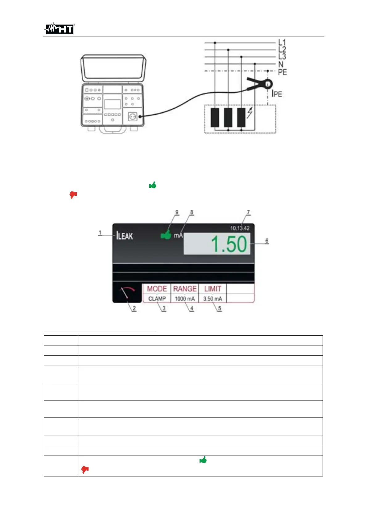
Fig. 72 : Connection of current clamp in I
LEAK measurement
8. Start the measurement by pressing the START/STOP key. The measurement will
start to run and will be stopped after pressing the START/STOP key again.
Measurement result will be currently displayed in green color if it is lower than or
equal to set limit value or in red color if it is higher than set limit value. Final result
will be equipped with green
symbol and with acoustic sound if it is OK or with
red
symbol and with longer acoustic sound if it is not OK. See the display
outlook with test result on the Fig. 73
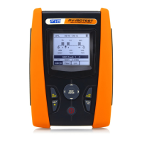
Fig. 73 : Visualization of ILEAK test result
Meaning of symbols on the display
Item Description
1 Selected function
2 Measurement screen touch-screen key
3
MODE touch-screen key to select measurement mode (CLAMP).
Currently selected mode is displayed on the bottom of the key
4
RANGE touch-screen key to select the CLAMP measurement range.
Currently selected range is displayed on the bottom of the key
5
LIMIT touch-screen key to select limit leakage current. Currently selected
value is displayed on the bottom of the key
6
Measurement result (in green colour - result OK, in red colour - result not
OK).
7 Real time clock (hh.mm.ss).
8 Measurement unit of result
9
Measurement result status (symbol
in green color - result OK, symbol
in red color - result not OK).)