9.2 Electrical system
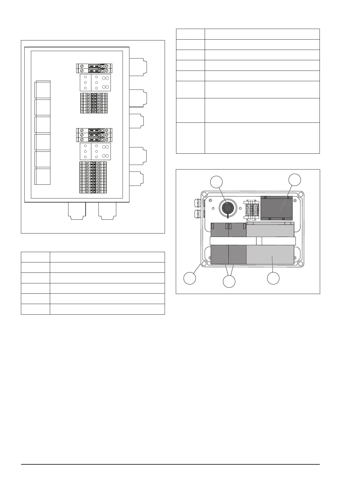
9.2.1 Fuses and relays
K11
K12
K13
K14
K21
K22
F11
F12
X10
X1:1-7
F21
F22
F23
X20
X2:1-11
W05
W06
W08
W07
W04
W03
W01
Table 2: Fuses
Fuse
Function
F11 12V fuse for ignition lock
F12 12V fuse for DC/DC converter
F21 24 VDC fuse for right drive engine
F22 24 VDC fuse for left drive engine
F23 24 VDC fuse for radio system
Table 3: Relays
Relay Function
K11 Radio system
K12 Right drive engine
K13 Left drive engine
K14 Activates DC/DC converter
Engine Bypasses the oil pressure guard and emis-
sion control module during start.
K21 Enables a RUN signal to the engine when
the radio control unit is activated and the
emergency stop is not activated.
K22 Shuts down the ignition system when the
radio control switch =1, the radio control
unit and the emergency stop is not activa-
ted .
9.2.2 Badan tterybox
1. Enclosure
2. Drive batteries
3. Main power switch
4. DC/DC converter
5. Start battery
DC/DC Converter
The DC/DC converter change 12V voltage to 24V
charging voltage for the batteries of the drive motors.
The charging voltage must be 27,4VDC +/- 0,2V.
Emission module
The emission module examines the emission values. If
the values are below the approved limit, the led bulb of
the emission module does not come on. If the values
increase above the approved limit, the led bulb of the
emission module comes on and the engine stops. When
the engine starts the emission module waits 1 - 2
minutes before it examines the values.
26 - Technical data 888 - 001 -