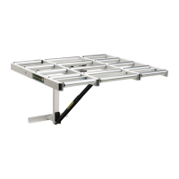
9. PivottheRollerFramebackoverandattachtheupperendofthe
SupportArmtotheAdjustmentPlateLusingaPivotRodGand(2)two
Acorn Nuts F.
10. Insert(2)91/2"RollersintoRollerFrameasshowninFigure7&8.Use
thinputtyknife(orsomethingsimilar)tocompressthespringloadedaxle.
Note:Itisveryimportanttoinstalltherollerswithfixedendinoutsideframe.
YouarenowreadytomakethefinaladjustmentstoyourOutfeedRoller.
11.Layastraightedgeonsawtabletopextendingouttofirstrollerclosest
tosawtable(Figure9).AdjustpositionofMainFrametobringbothends
ofrollerslevelwithsawtabletop.Tableremainsfoldeddown—cams
positionedasinFigure3&4.TightentopMainFramenutsandbolts.
12.Swingrollersectionintoit’sextendedposition.Tightenorloosen
AdjustmentBolttobringoutboardrollerslevelandparallelwithsawtable
top.TightenthetoplevelingbracketmountingboltsFigures10&11.
13.DoublecheckandmakesureRollerSectionismountedlevelwiththe
sawtabletop(sidetoside).Thenmarkanddrilllowermountingholes.
Install(2)5/16"-18x1"boltswithflatwashersthroughtheoutsideof
thesawcabinet,withflatwashersH,lockwashers I,and5/16"-18
nuts Jontheinside.Tightensecurely.
Note:Beforedrillingthelowermountingholesonsomesawmodelsyou
mayfindtheangleddustpanwithinthecabinetbecomesanobstruction
toproperinstallation.YoumaywanttoadjustthepositionofLowerMain
FrameBracket.
14.Measuretheapproximatedistancebetweenthemountingholesonthe
MainFrameBracket.
15.Fromtheinsideofthecabin,usingthemeasurementfromStep14,
measurefromthetopholesdowntodeterminetheapproximatelocation
lflowermountingholes.Theymayfallabovethedustpan,belowthepan
orstraddlethepan.
16.Iftheapproximatelocationoftheholesfallabovethepan,proceedwith
normalinstallation.Ifthemountingboltswillfallbelowthedustpan,
proceedtothenextstep.
17.Ifthedustpanismountedtothecabinetusingscrewsandthestudfalls
belowthepan,thepancanberemovedtocompletetheinstallation.
18.Ifthedustpanisweldedinandtheholeswillfallbelowthedustpan,the
boltscanbeinstalledfromthebottom,bytippingofblockingthesawup.
Useextremecautionwhenworkingonthesawfromthebottom.
19.PositionCamNsoRollerFrameisinthelowerposition.Makesuremiter
gaugeguidebarrestslevelonfirstroller.
Re-checkandtightenallfasteners.
10
Figure 11
Figure 7
Figure 8
Cam
13"
9
1
/
2
"
Pivot Pin
This End Must Be
Inserted First
Figure 9
Figure 10

 Loading...