30
LP-387 REV. 12.15.14
H. PIPING INSTALLATION
This boiler should not be operated as a potable hot water heater. It should not be used as a direct hot water heating device.
Basic steps are listed below that will guide you through the installation of the boiler.
1. Connect the system return marked “Boiler Return”.
2. Connect the system supply marked “Boiler Supply”.
3. Install a purge and balance valve or shut off valve and drain on the system return to purge air out of each zone.
4. Install a back flow preventer on the cold feed make-up water line.
5. Install a pressure reducing valve on the cold feed make-up water line (15 psi nominal on the system return). This boiler has a
maximum working pressure of 160 psi. You may order a higher pressure relief valve kit from the factory. Check temperature and
pressure gauge when operating. It should read a minimum pressure of 12 psi.
6. Install a circulator as shown in piping details (this section). Make sure the circulator is properly sized for the system and friction loss.
7. Install an expansion tank on the system supply (see Part 5, Section D for water volume). Consult the expansion tank manufacturer’s
instructions for specific information relating to expansion tank installation. Size the expansion tank for the required system volume and
capacity.
8. Install an air elimination device on the system supply.
9. Install a drain valve at the lowest point of the system. NOTE: The boiler cannot be drained completely of water without purging the
boiler with an air pressure of 15 psi.
10. The relief valve and temperature and pressure gauge are included in the boiler accessory kit. A pipe discharge line should be
installed 6” above the drain in the event of pressure relief. The pipe size must be the same size as the relief valve outlet. NEVER
BLOCK THE OUTLET OF THE SAFETY RELIEF VALVE.
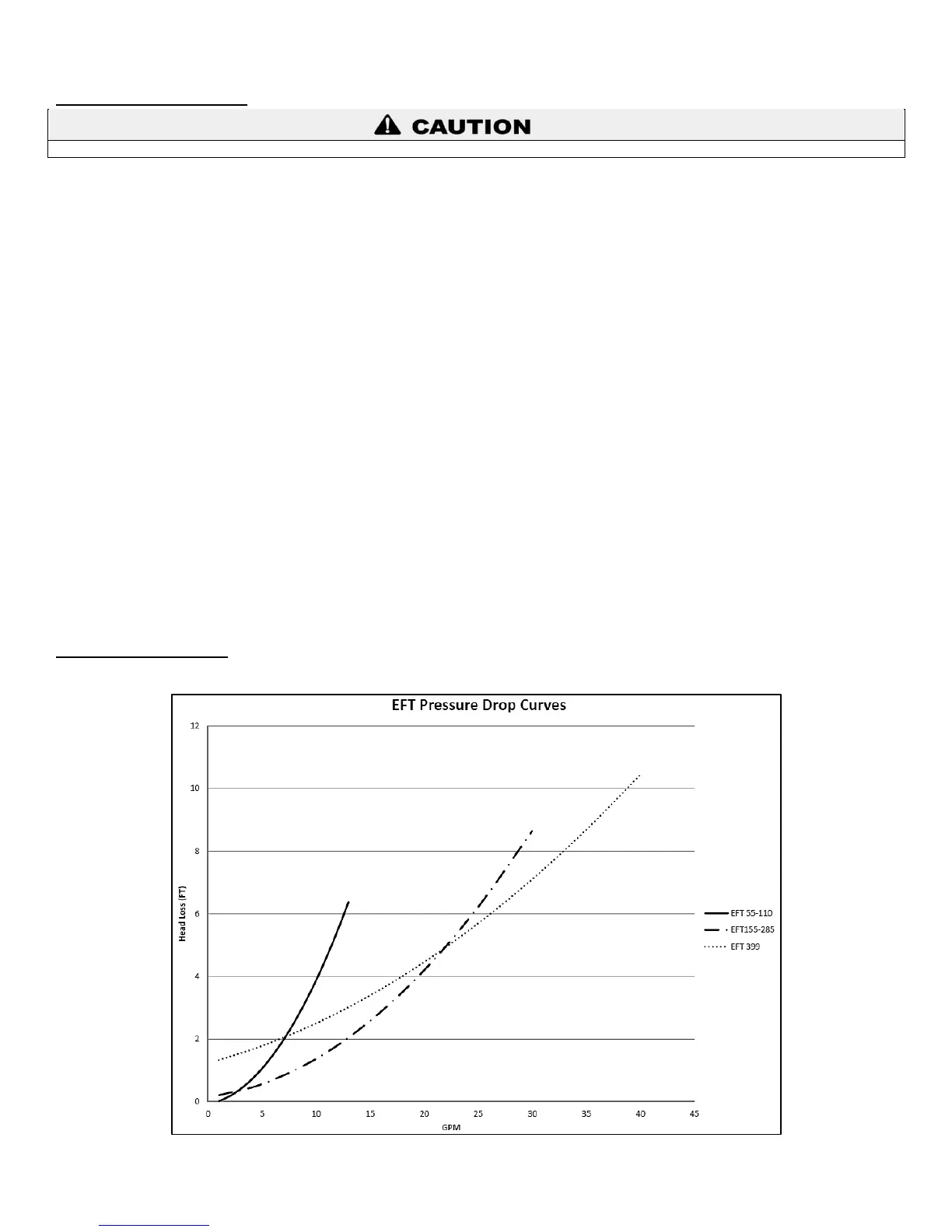
I. CIRCULATOR SIZING
The heat exchanger has a pressure drop that must be considered in your system design. Refer to Table 4 for pressure drop through the
heat exchanger.
Table 4 – Boiler Pressure Drop