LP-743 Rev. 000 Rel. 000 Date 8.25.20
3
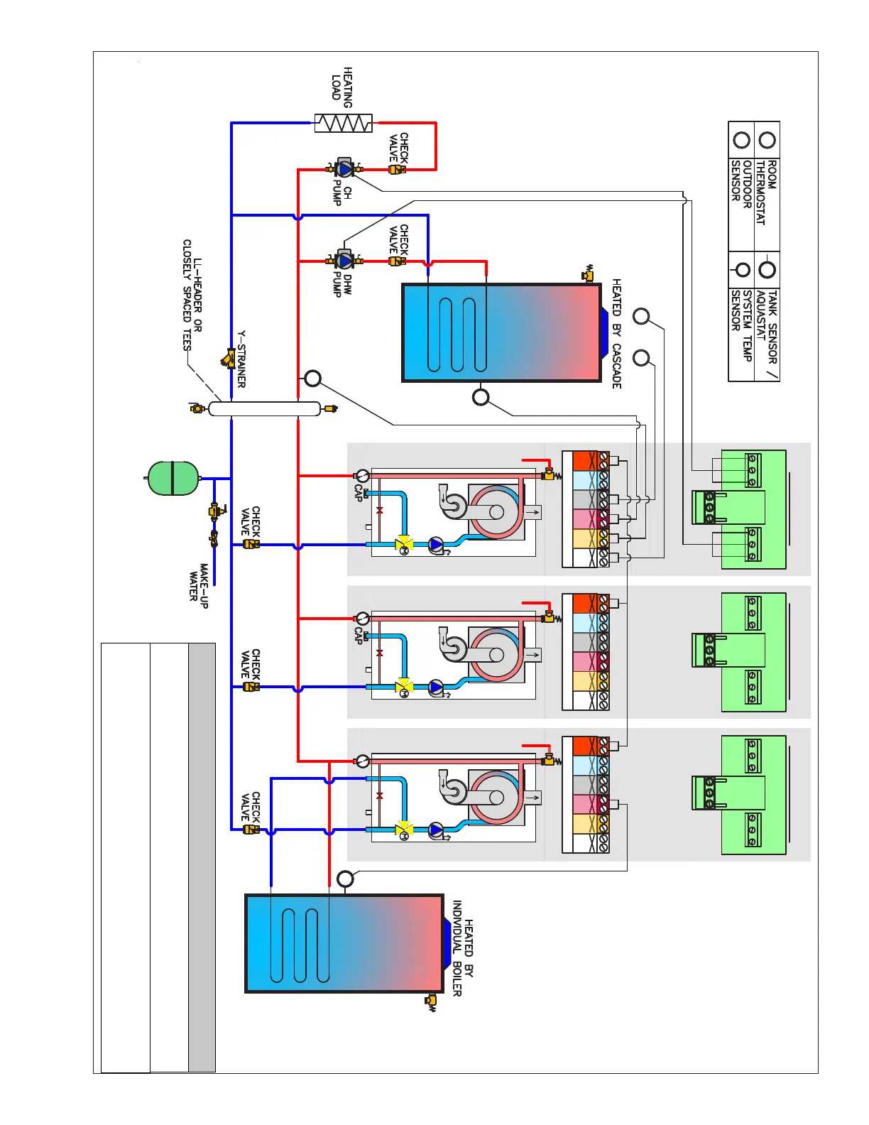
Figure 1 - Three (3) Cascaded Boilers with Upstream or Downstream Indirect Water Heater - Piping and Wiring for ELU-85WBN, ELU-120WBN, ELU-120WCN, ELU-150WCN Models ONLY
S
TS
TS
TS
S
BUS
T B
120V
TT2
120V
OD
5V IN
120V
TNK
120V
SYS
120V
TT1
120V
PCB / CONTROL PANEL
BUS
T B
120V
TT2
120V
OD
5V IN
120V
TNK
120V
SYS
120V
TT1
120V
PCB / CONTROL PANEL
DHW
PUMP
CH
PUMP
120VAC JUNCTION BOX
DHW
PUMP
CH
PUMP
120VAC JUNCTION BOX
BUS
T B
120V
TT2
120V
OD
5V IN
120V
TNK
120V
SYS
120V
TT1
120V
PCB / CONTROL PANEL
RT
DHW
PUMP
CH
PUMP
120VAC JUNCTION BOX
OD
OD
MASTER FOLLOWER
RT
FOLLOWER
DOWNSTREAM
INDIRECT FIRED
WATER HEATER
UPSTREAM
INDIRECT FIRED
WATER HEATER
Piping for Models:
ELU-85WBN, 120WBN, 120WCN, 150WCN
In this plumbing application, parameter 25.1.6 needs to be adjusted to setting 1.
This ensures the CH pump will not operate during DHW demands.
Follow the Establishing Boilers as Master and Followers instructions when
connecting to the BUS terminals. Connecting to the BUS terminals without
following these instructions could damage the main PCB.
 Loading...