2
The installation site must be well ventilated, and the air vents of the router must not be blocked.
Do not place the router in a dusty environment.
Leave more than 100 mm clearance at two sides and rear of the router for heat dissipation.
100mm
Installing the Router
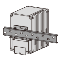
Scenario 1: Mounting the Router on a DIN Rail
4.1 Installing the AR530 Series Industrial Switching Router
Screw lock nuts on the hex bolts and fix the hex bolts on the mounting bracket.
1
NOTE
Before the installation, ensure that the DIN rail has been secured in position.
The router is placed near the DIN rail for convenient movement.
1
Lock nut
3
3
Hang the mounting bracket on the DIN rail.
Use a combination wrench to screw the two hex bolts on the mounting bracket. When the DIN rail is fixed
with the raised hex bolts, tighten the lock nuts by rotating the wrench counterclockwise.
Align an M4x20 screw with the topmost tapped hole on the mounting bracket, and screw it about 5 mm
into the tapped hole with a Phillips screwdriver.
Use two M4x20 screws to fix the stainless steel sheet on the router.
4
5
2
6
L1 L2
L3
FE5
FE4
FE3
FE2
N
A
RS485-
0
B
A
RS485-
1 DI-0
DI-1
B
GE0
RX TX
GE1
MONI
TO
R
Power Outage Survival
RX TX
FE6
FE7
CONSOLE
6
Loosen the screws on the front top cover with the Phillips screwdriver, remove the front top cover, and
keep it in an appropriate place for later use.
Hang the router onto the topmost screw on the mounting bracket and adjust position of the router to
align the mounting holes on the router with those on the mounting bracket. Use two M4x30 screws to fix
the router onto the mounting bracket and tighten the topmost screw on the mounting bracket.
7
5
 Loading...