3
Attach the mounting bracket against the wall and adjust its position to keep the top and bottom
edges horizontal. Mark positions of the four mounting holes with a marker.
1
1
120mm
130mm
Adjust position of the mounting bracket to align the mounting holes on it with the four marked
positions on the wall.
Use four M4 screws to secure the mounting bracket on the wall.
a
b
Secure the mounting bracket on the wall.
2
2
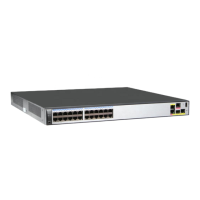
AR530
Series
INFRARED
PWR
RUN/AL
M
RS485-0
RS485-1
AR531-F2C-
H
Align an M4x20 screw with the topmost tapped hole on the mounting bracket, and screw it about 5 mm
into the tapped hole with a Phillips screwdriver.
Use two M4x20 screws to fix the stainless steel sheet on the router.
3
4
L1 L2
L3
FE5
FE4
FE3
FE2
N
A
RS485-
0
B
A
RS485-
1 DI-0
DI-1
B
GE0
RX TX
GE1
MONI
TO
R
Power Outage Survival
RX TX
FE6
FE7
CONSOLE
1
5
7
4
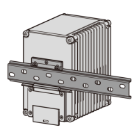
Scenario 2: Mounting the Router on a Wall
The panel with interfaces must face down to protect the interfaces from water.
Ensure that there are no flammable or explosive materials near the router and no sundries within 100 mm around
the router.
CAUTION
 Loading...