4
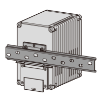
Scenario 3: Mounting the Router in a Cabinet (Using a 530 Horizontal Rack-Mounting Kit)
There must be a clearance larger than or equal to the router's width at the left and right of the router after the
installation. The clearance above the router must be at least two times the router's height and the clearance below
the router must be greater than or equal to the router's height.
CAUTION
AR530
Series
INFRARED
PWR
RUN/ALM
RS485-0
RS485-1
AR531-F2C-H
5
Loosen the screws on the front top cover with the Phillips screwdriver, remove the front top cover, and
keep it in an appropriate place for later use.
Hang the router onto the topmost screw on the mounting bracket and adjust position of the router to
align the mounting holes on the router with those on the mounting bracket. Use two M4x30 screws to fix
the router onto the mounting bracket and tighten the topmost screw on the mounting bracket.
6
1
Use two M4x20 screws to fix the stainless steel sheet on the router.
Loosen the screws on the front top cover with a Phillips screwdriver, remove the front top cover, and keep it
in an appropriate place for later use.
Hang the router onto the topmost screw on the 530 horizontal rack-mounting kit and adjust position of the
router to align the mounting holes on the router with those on the rack-mounting kit. Use two M4x30
screws to fix the router onto the rack-mounting kit and tighten the topmost screw on the rack-mounting kit.
2
3
6
L1 L2
L3
FE5
FE4
FE3
FE2
N
A
RS485-
0
B
A
RS485-
1 DI-0
DI-1
B
GE0
RX TX
GE1
MONI
TO
R
Power Outage Survival
RX TX
FE6
FE7
CONSOLE
1
2
1
2
3
×4
2U
4
 Loading...