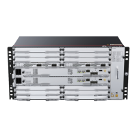
This document serves as a Quick Installation Guide for the NetEngine 8000 M14, PTN 6900-2-M14, and NE40E-X2-M14 devices, focusing on their installation within IEC 19-inch and ETSI 21-inch cabinets. The guide provides essential information for trained and qualified personnel to ensure safe and proper installation, operation, and maintenance.
Function Description
The document outlines the process of installing the chassis, cable management frames, and various components such as interface boards, main control boards, and optical modules. It also details the connection of different types of cables, including PGND, DC power, AC power, E1, optical fiber, Ethernet, and 75-ohm coaxial cables. The guide emphasizes adherence to safety regulations and precautions throughout the installation process, ensuring both personal and equipment safety. It also provides guidelines for site requirements, cabinet requirements, and post-installation checks to verify proper device operation.
Important Technical Specifications
Chassis Dimensions and Weight:
- Chassis height: 5 U for both DC and AC chassis.
- Dimensions without packaging (H x W x D): 222 mm x 442 mm x 220 mm (8.74 in. x 17.4 in. x 8.66 in.) for both DC and AC chassis.
- Weight without packaging (base configuration):
- DC Chassis: 10.1 kg (22.27 lb)
- AC Chassis: 14.6 kg (32.19 lb)
Power Specifications:
- Rated input voltage:
- DC Chassis: -48 V/-60 V
- AC Chassis: PTN devices: 110 V/220 V; Other devices: 200 V to 240 V /100 V to 127 V dual live wires, supporting 240V HVDC.
- Input voltage range:
- DC Chassis: -40 V to -72 V
- AC Chassis: 90 V to 290 V
- Maximum input current:
- NetEngine 8000 M14/PTN 6900-2-M14/NE40E-X2-M14 (DC): 60 A
- NetEngine 8000 M14/PTN 6900-2-M14/NE40E-X2-M14 (AC): 10 A
Environmental Requirements:
- Long-term operating temperature:
- DC: -40°C to +65°C
- AC: -20°C to +55°C
- Storage temperature: -40°C to +70°C
- Relative operating humidity (non-condensing):
- Long-term: 5% to 85% RH
- Short-term: 5% to 95% RH
- Relative storage humidity (non-condensing): 5% to 95% RH
- Long-term operating altitude: ≤ 4000 m (Operating temperature decreases by 1°C every 220 m increase in altitude between 1800 m and 4000 m).
- Storage altitude: < 5000 m
Cabinet Requirements:
- Type: IEC 19-inch or ETSI 21-inch cabinet. Huawei A63B cabinet is recommended.
- Depth: Greater than or equal to 300 mm.
- Cabling space: Distance between cabinet door and device board should be greater than or equal to 120 mm.
- Ventilation clearance: At least 75 mm on the left and right sides of the device in a 19-inch cabinet.
- Cabinet door porosity: Greater than 50% for heat dissipation.
- Installation accessories: Must include guide rails, floating nuts, and screws.
- Ground terminal: Required for connecting to the device.
- Cable outlet: On the top or bottom for overhead or underfloor cabling.
Cable Specifications:
- DC Power Cable Fuse Capacity: ≥63A, ≤80A (10 mm² cables for 63 A breakers, 16 mm² cables for >63 A breakers).
- DC Power Cable Size: 16mm², 10mm² (0-14 meters) recommended; 16mm² (15-23 meters) recommended.
- AC Power Cable Fuse Capacity: ≥10A, ≤16A (10 A circuit breaker at user side for hierarchical power supplying protection).
- Optical Fiber Bending Radius: Single-mode G.657A2: no less than 10 mm; Multi-mode A1b: no less than 30 mm.
- Corrugated Pipe Capacity: 32 mm diameter pipe accommodates max 60 fibers (2 mm diameter each).
- Corrugated Pipe Length: Approximately 10 cm inside a cabinet.
- Ethernet Cables: Flat-door cabinets (N63B/N63E) support max 6 shielded Ethernet cables per layer of interface boards. Convex-door cabinets (A63B/A63E) support max 16 shielded Ethernet cables per layer of interface boards. Two Ethernet cables are required for NMS server connection (active and standby main control boards).
Usage Features
Installation Flexibility:
- The device can be installed in both IEC 19-inch and ETSI 21-inch cabinets, with specific instructions for each type, including configurations with front columns and middle columns.
- DC and AC chassis are installed similarly, with the DC chassis used as a primary example in the guide.
Component Installation:
- Detailed steps are provided for installing interface boards and main control boards, including handling ejector levers and captive screws.
- Optical modules are installed by inserting them fully into the optical port, followed by connecting optical fibers.
Cable Management:
- The guide emphasizes proper cable routing to prevent blocking air vents and ensure heat dissipation.
- Temporary and formal labels are recommended for cables.
- Specific routing guidelines are provided for different cable types (power, E1, optical fiber, Ethernet) and their placement within the cabinet (e.g., left side for power module maintenance).
- Instructions for handling corrugated pipes for optical fibers are included, specifying length and capacity recommendations.
Safety and ESD Protection:
- Strict adherence to safety regulations and precautions is mandatory, including wearing ESD wrist straps and gloves.
- Warnings against installing or removing equipment/power cables while power is on, and the necessity of grounding the equipment before powering it on.
- Caution against laser beams and direct eye exposure to optical modules/fibers.
- Guidelines for handling chassis to prevent damage during transport and installation (e.g., moving upright, not dragging).
- Instructions for handling cards and modules, including not opening ESD bags until delivery to the equipment room and avoiding using connectors to support card weight.
Maintenance Features
Pre-Power-on Checks:
- Before powering on the device, users must verify the installation of fixed optical attenuators, check the fuse capacity of the external power supply, and confirm normal external power supply voltage.
Power-on Check and Troubleshooting:
- A table describes the expected states of indicators (PWR, FAN, STAT, PROG, L/A) for power modules, fan modules, main control boards, and interface boards when the device is operating properly (steady green).
- Troubleshooting procedures are provided for abnormal indicator states, such as steady red (signals lost on optical port) or steady off (module not detected). These procedures include checking peer chassis/boards, fiber connections, optical attenuators, cleaning fiber connectors, and replacing damaged fibers or boards.
Optical Fiber Maintenance:
- The guide highlights the importance of using Huawei-certified optical modules for reliability and service stability.
- Dust-proof caps must be installed on unused optical ports.
- Instructions for proper insertion of optical modules and connecting optical fibers are provided, along with a check for the LINK indicator.
- An appendix details the importance of inspecting and cleaning optical fiber connectors and adapters, especially for 50G optical module links using PAM4 encoding technology, to prevent signal interference and unstable connections.
Documentation and Support:
- Information on how to obtain product documentation and technical support is provided for both enterprise and carrier users, including links to Huawei's technical support websites and support communities.