10. Taking Photos for Acceptance
8. Installing Cables (Continued)
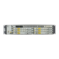
P&E port
System status
indicator
Connecting to PoE power
supply devices
In normal cases, the system status indicator
is steady green.
9. Checking the Power Status
Acceptance point 1: photo
of the overall site
Acceptance point 2:
MAC address
Acceptance point 3:
antenna azimuth angle
Take photos one by one based on the following acceptance points. After the deployment,
attach the photos to the acceptance checklist.
Acceptance point 6:
AP connector
Acceptance point 5: AP
antenna connector
Acceptance point 4:
antenna elevation angle
Acceptance point 7: AP and outdoor
network cable grounding
NOTE
a
b
c d
e
1. Install the RF cables.
1. The RF ports connected to the same RF cable must have the same polarization direction.
2. Waterproof and anticorrosion measures must be taken for the RF ports of the AP antenna.
1. When installing an AP on a tower, route the outdoor network cable from the tower body
to the outdoor cable tray and ground it 1 m away from the outdoor cable tray.
2. Ground the outdoor network cable 0.5 m to 1 m away from the equipment room or
outdoor cabinet, except in the following cases: The AP is connected to equipment that
can be installed outdoors, such as PC500 or outdoor PI; the distance between the tower
and the outdoor cabinet/equipment room is less than 5 m.
3. Apply waterproofing and anti-corrosion treatments on the grounding points.
Network cable
grounding clip
3. (Optional) Insert the optical module into the
GE(o) port and install outdoor optical fibers.
2. Install outdoor network cables.
Insert fibers into
the GE(o) port.
Push the inner
cylinder to the top.
Push the shell to
the top, turn the
shell clockwise,
and tighten the
socket.
Inner cylinder
Rubber washer
Shell
a
b
c
NOTICE
NOTE
1. Acceptance points 3 and 4: The scales of the azimuth and elevation angles of
the RT need to be provided.
2. Acceptance points 5 and 6: The RF cable connection between the antenna and
the AP is provided. That is, H is connected to H, V is connected to V, or two RF
cables are identified using the color-coding.
NOTE

 Loading...