Do you have a question about the Huawei RRU3908 V2 and is the answer not in the manual?
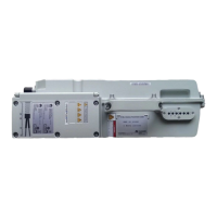
Describes the exterior, panels, LEDs, and cables of the RRU3908 V2.
Lists the product versions related to this document.
Identifies the target readers for this document.
Outlines the structure and chapter progression of the document.
Defines symbols used in the document and their meanings.
Explains general formatting conventions like font styles and usage.
Details conventions for command line syntax and arguments.
Explains conventions for graphical user interface elements and navigation.
Describes conventions for keyboard input and key combinations.
Explains conventions for mouse actions like click and drag.
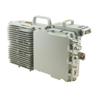
Describes the modular structure and external ports of the RRU.
Details the bottom panel, cabling cavity panel, and LED area of the RRU module.
Explains the function of the six LEDs used to display the RRU's running status.
Lists the various cables used with the RRU3908, including PGND, power, and optical cables.
Ensures the grounding of the RRU and describes its exterior and terminals.
Describes the -48 V DC shielded power cable for the DC RRU.
Feeds AC power from external equipment to the AC RRU.
Feeds power to the AC RRU and monitors its running status.
Transmits CPRI signals between the BBU and the RRU or between RRUs.
Transmits alarm signals from external equipment to the DC RRU.
Transmits and receives RF signals between the RRU and antenna.
Connects ports of two RRUs and transmits RF signals between them.
Transfers control signals from base station to RET antenna.
Used to provide surge protection for AC power.
Used for installing RRUs indoors.
Interconnects cables of different core diameters for long-distance power transfer.
| Product Type | Remote Radio Unit |
|---|---|
| Model | RRU3908 V2 |
| Supported Standards | LTE |
| Power Supply | -48 V DC |
| Weight | 15 kg |
| Operating Temperature | -40°C to +55°C |
| Cooling Method | Natural convection |
| Protection Level | IP65 |
| Frequency Bands | 1800 MHz, 2100 MHz |
| MIMO | 2T2R |
| Humidity | 5% to 95% |
| Installation Mode | Pole, wall |
| Interface | CPRI |