Item Label Description
ACT
VSWR
CPRI0
CPRI1
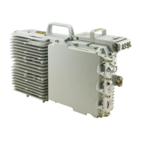
(2) Cabling cavity
panel
RTN(+)0 Power supply port
NEG(-)0
RTN(+)1 Cascaded power supply port
NEG(-)1
RX TX CPRI0 Optical/electrical port 0
TX RX CPRI1 Optical/electrical port 1
EXT_ALM Alarm port
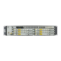
(3) Bottom panel of
the RRU
RX_IN/OUT RF interconnection port
RET RET antenna port
ANT_TX/RXA RF TX/RX port A
ANT_TX/RXB RF TX/RX port B
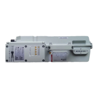
(4) Bottom panel of
AC conversion
module
AC-in AC power supply socket
DC-out DC power supply socket
2.3 LEDs on the RRU
The six LEDs on the RRU are used to display the running status of the RRU.
For details on the positions of the LEDs on the panel of the RRU, see 2.2 Panels of the RRU.
Table 2-2 describes the LEDs on the RRU.
Table 2-2 LEDs on the RRU
LED
Color Status Description
RUN Green On There is power supply, but the board is faulty.
Off There is no power supply, or the board is
faulty.
Blinking (on for
1s and off for 1s)
The board is running properly.
2 Introduction to the RRU3908
RRU3908 V2
Hardware Description
2-6 Huawei Proprietary and Confidential
Copyright © Huawei Technologies Co., Ltd.
Issue 02 (2010-10-25)
 Loading...