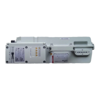
Exterior
The alarm cable has a DB15 connector at one end and eight cord-end terminals at the other end.
Figure 3-10 shows the alarm cable.
Figure 3-10 Alarm cable
Pin Assignment
Table 3-12 describes the pin assignment for the wires of the alarm cable.
Table 3-12 Pin assignment for the wires of the RRU alarm cable
RRU
Alarm
Port
Pin of the
DB15
Connecto
r
Wire
Color
Wire
Type
Cord End
Terminal
Description
Dry
contact
X1.2 White/blue Twisted
pair
X2 SWITCH_INPUT0+
X1.3 Blue X3 SWITCH_INPUT0-
(GND)
X1.6 White/
orange
Twisted
pair
X4 SWITCH_INPUT1+
X1.7 Orange X5 SWITCH_INPUT1-
(GND)
RS485 X1.10 White/
green
Twisted
pair
X6 APM RX-
X1.11 Green X7 APM RX+
X1.13 White/
brown
Twisted
pair
X8 APM TX-
X1.14 Brown X9 APM TX+
3 RRU Cables
RRU3908 V2
Hardware Description
3-12 Huawei Proprietary and Confidential
Copyright © Huawei Technologies Co., Ltd.
Issue 02 (2010-10-25)

 Loading...