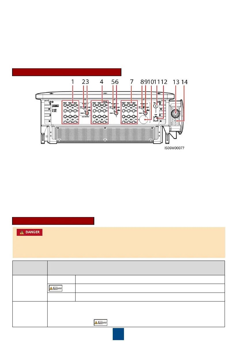
DC input terminals (controlled by DC SWITCH 1)
(2) DC switch 1 (DC SWITCH 1)
(3) DC input terminals (controlled by DC SWITCH 2)
(4) DC switch 2 (DC SWITCH 2)
(5) DC input terminals (controlled by DC SWITCH 3)
(6) DC switch 3 (DC SWITCH 3)
(9) Communications port (COM)
(10) Hole for the AC output power cable
(11) Hole for the tracking system power cable
Port Illustration (Automatic DC Switch)
DC input terminals (controlled by DC SWITCH 1
(2) DC switch 1 (DC SWITCH 1)
(4) DC input terminals (controlled by DC
SWITCH 2)
DC switch 2 (DC SWITCH 2)
(7) DC input terminals (controlled by DC SWITCH 3)
(8) DC switch 3 (DC SWITCH 3)
12) Communications port (COM)
13) Hole for the AC output power cable
14) Hole for the tracking system power
DC Switch Description
The DC switches automatically turn off when a fault occurs in the inverters (LED4 is steady red,
and the three DC switches are OFF). In this case, contact your technical support. Do not turn on
the DC switches by yourself.
The DC switch is ON and can automatically turn off for protection.
The DC switch is ON but cannot automatically turn off for protection.
When the DC switch automatically turns off for protection, the RESET button
will be released.
•
When the RESET button is not pressed, the DC switch can only be turned to the
unloaded position , and cannot be set to the ON position.
 Loading...