Pub. 42004-554A
E3 Speaker Master and Remote Modules Page 2 of 6
P:\Standard IOMs - Current Release\42004 Instr. Manuals\42004-554A.docx
08/20
E3 Module Location
Install the speaker master module(s) with other CAN bus devices in the same cabinet as the E3 controller.
Install the modules horizontally in snap-track style mountings for optimum arrangement. Install the
speaker remote modules at the speakers.
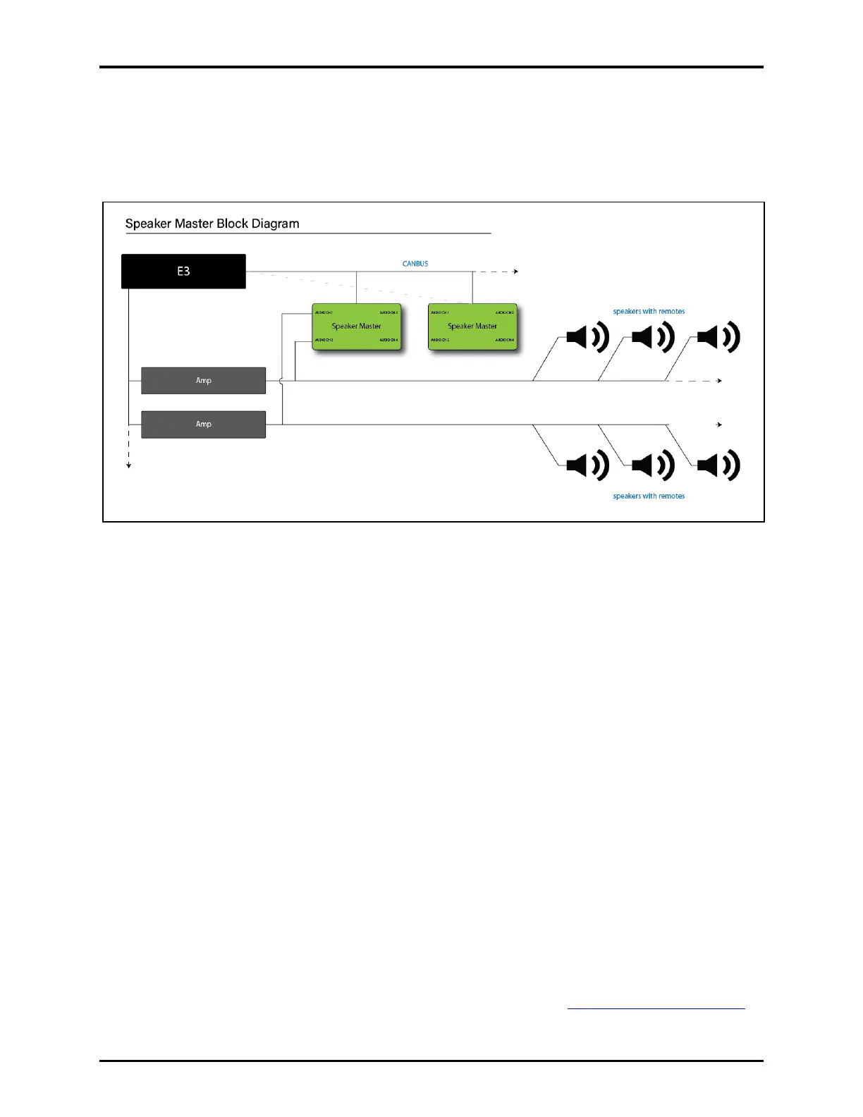
Figure 1. E3 Speaker Master and Remote Modules Block Diagram
Installation
Speaker Master Modules
1. Connect the CAN bus cable from the Elemec3 controller to the CAN IN RJ-45 jack on the speaker
master module.
Daisy chain multiple CAN bus modules using the CAN IN and the CAN OUT connectors.
2. For power from the CAN bus cable: Move jumper, P5, to the CAN position.
NOTE: The current requirement of the connected devices must not exceed the CAN bus cable rating.
3. For separate dc power (not over the CAN data link cable): Terminate the 24 V dc power supply at
pluggable terminal block P1.
1. Use pluggable terminal block P2 to connect 24 V dc power to the next speaker master controller,
if necessary.
2. Move jumper, P5, to the LCL position.
NOTE: The current requirement of the connected devices must not exceed the local power supply rating.
4. Make the speaker zone audio line (parallel) connections at TB1–TB4.
5. Configure the speaker master module and speaker remote modules in the E3 Console application.
Instructions for using the E3 Console are in Pub. 42004-550, Elemec3 Console Manual—Version 3.0.
GAI-Tronics’ documentation is located on the GAI-Tronics website at https://www.gai-tronics.com.
6. Apply power to the central amplifier, speaker master module, and Elemec3 controller.

 Loading...