24
LOW WATER CUT-OUT
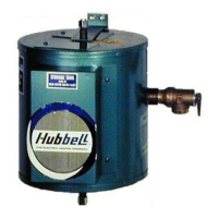
1. Due to the low resistivity of DI/RO water, a 316L stainless steel float type low water cut-
out is supplied in lieu of a conductivity type. This device will help protect the elements
from energizing when there is insufficient water in the tank. The float type low water cut-
out will disengage the control circuit during low/no water conditions and will auto-reset
when the water reaches a safe level. The conductivity low water detection system
incorporated in the T1000 digital controller should be disabled for DI/RO water
applications.
DISPLAY BUTTONS
1. If the display randomly changes or does not respond when the buttons are pressed,
loosen the four (4) screws holding the display to the base, reseat the display in the
center of the opening, and re-tighten the screws.
MISCELLANEOUS
1. If the display flashes when the unit is first turned on or turned on after maintenance,
check that the J5 terminal on the controller is engaging all four pins on the board.
2. Note that before replacing the control board, display, or probe, it is recommended that
the power supply to the heater be turned off at the main circuit breaker disconnect to
the heater to reset and clear the electronic controller.
GENERAL TROUBLESHOOTING
Symptom Probable Cause Corrective Action
Water reaches setpoint
temperature but does
not last through the
entire process cycle.
Low incoming water
temperature.
Incoming water temperature must be
adequate for the heater size. Increase the
incoming water temperature.
Incoming water
temperature is dropping.
Primary water supply is not adequate to
continually provide correct temperature in
sufficient quantities. Increase the supply of
primary cold water.
Heater may be
undersized.
The heater must be properly sized for the
incoming water and rinse requirements of
the process. If required, replace with a
properly sized unit.
Incorrect voltage. Voltage available at the heater must be
correct for unit. Verify voltage on all
phases matches nameplate on the heater.
If two magnetic
contactors are utilized,
one is not energizing.
Verify that both magnetic contactors are
operating. If not, see the ‘Magnetic
Contactor Troubleshooting’ section.
One or more elements
are not energizing.
Verify that each element is drawing the
correct amperage. Replace elements as
required.
Temperature and
pressure relief valve
seeps.
Anti-siphon valve or
check valve installed in
the cold water inlet line.
Remove the anti-siphon valve or the check
valve to allow for the expansion of the
water or install a back pressure relief valve.