8
OPTIONAL EQUIPMENT
Slide Brackets
Available for the HD6 Model only, these brackets allow for mounting the water heater under a
counter. See slide bracket diagram on page 9 for details.
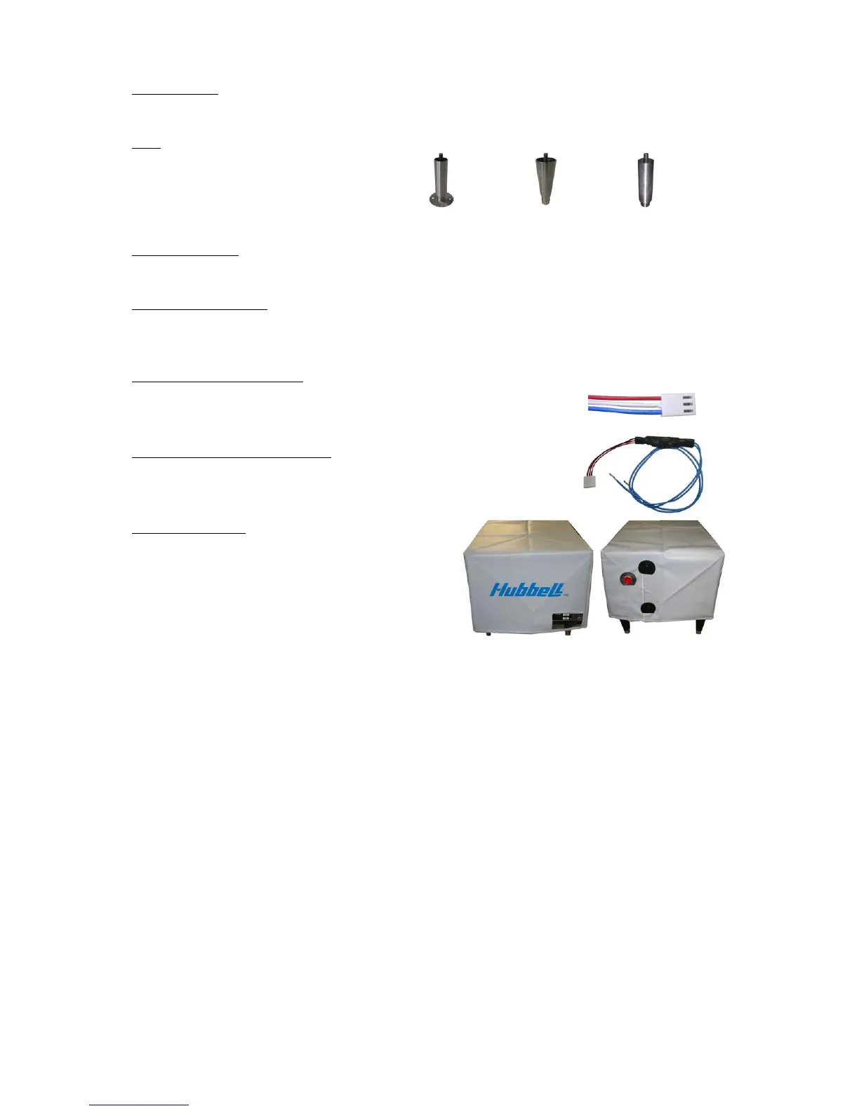
Legs
In lieu of the standard black plastic legs,
optional adjustable legs are available in
stainless steel, die-cast nickel plated, and
floor mount stainless steel. All optional
legs are adjustable height type. Floor Mount Nickel Plated Stainless Steel
Alternate Voltage
Other voltages are available, including 277V single-phase, and 380V, 415V, and 440V three-
phase. Consult the factory for details.
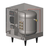
XB1 Expansion Board
An optional expansion board to the control board can be used to for additional circuit firing
when more than two circuits are required and/or as an auxiliary high or low temperature
alarm/relay. On models with three contactors the XB1 is supplied as standard.
Remote Alarm Plug Adapter
An optional plug adapter is available to provide a remote fault alarm
signal through the J4 connector on the control board. See page 11 for
installation details.
24-Volt Heater Interlock Adapter
An optional plug adapter is available to interlock the heater via a 24-volt
signal through the J1 connector on the control board. See page 11 for
installation details. (Only available with r23 or later software).
Protective Shrouds
An optional durable protective plastic shroud is
available to prevent damage to the heater due to
water intrusion. The cover fits snugly over the entire
heater and can be easily removed for cleaning and
service.
SECTION II – INSTALLATION AND START-UP
WARNING / CAUTION
• DO NOT TURN ON THE ELECTRIC POWER SUPPLY to this equipment until
heater is completely filled with water and all air has been released. If the heater is
NOT filled with water when the power is turned on, the heating elements will burn
out.
• For protection against excessive pressures and temperatures, local codes require the
installation of a temperature-and-pressure (T&P) relief valve certified by a nationally
recognized laboratory that maintains periodic inspection of production of listed
equipment of materials, as meeting the requirements for Relief Valves and Automatic
Gas Shutoff for Hot Water Supply Systems. ANSI Z21.22-1971. THE CUSTOMER
IS RESPONSIBLE TO PROTECT PROPERTY AND PERSONNEL FROM HARM
WHEN THE VALVE FUNCTIONS.
• All water heaters have a risk of leakage at some unpredictable time. IT IS THE
CUSTOMER'S RESPONSIBILITY TO PROVIDE A CATCH PAN OR OTHER
ADEQUATE MEANS, SO THAT THE RESULTANT FLOW OF WATER WILL
NOT DAMAGE FURNISHINGS OR PROPERTY.
• Installation or service of this unit requires ability equal to that of a licensed tradesman
in the field.