9
• The installation must conform to these instructions and any local authority having
jurisdiction. Grounding and electrical wiring connected to the unit must also conform
to the latest version of the National Electric Code NFPA-70.
WATER HEATER PLACEMENT
1. Place the heater on a solid, level foundation in a clean, dry location.
2. The water heater should be protected from freezing and waterlines insulated to reduce
energy and water waste.
3. Leave a minimum of 18” clearance for element withdrawal and control access.
4. Do not install in an area where flammable liquids or combustible vapors are present.
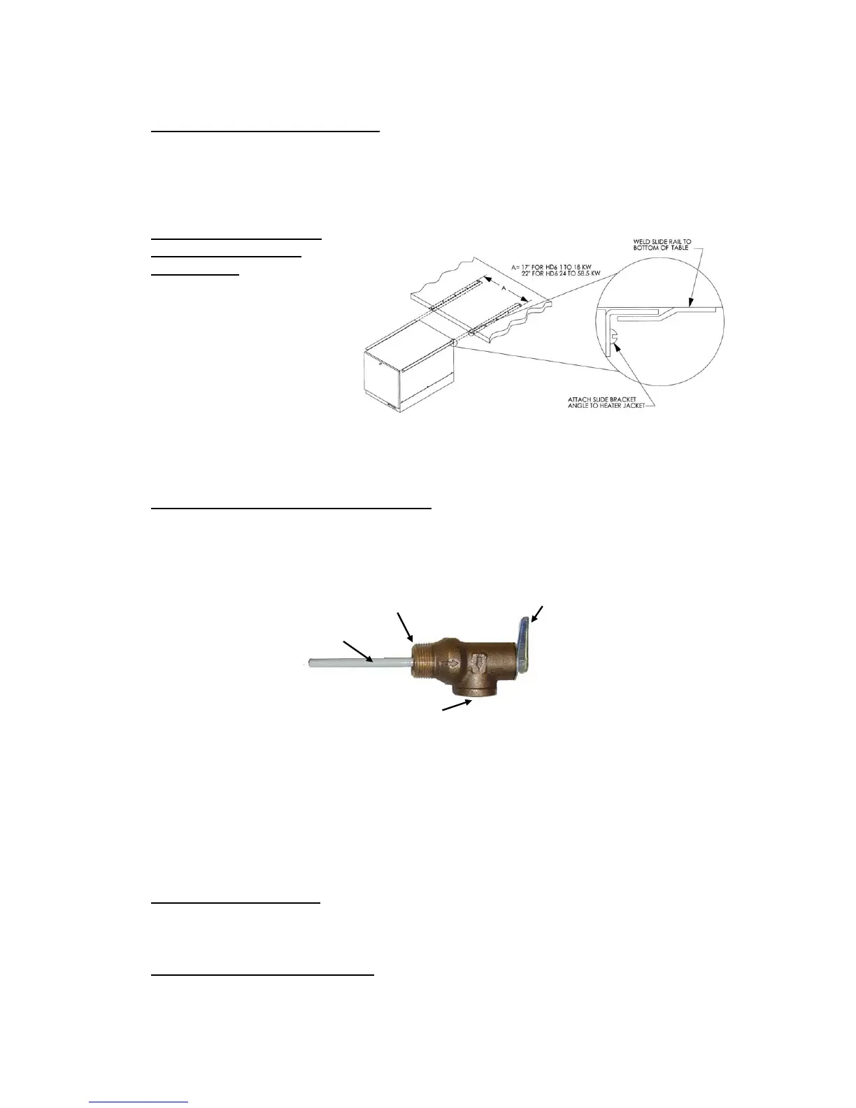
SLIDE BRACKETS FOR
HANGING SUPPORT
MOUNTING
1. Weld slide rails to
bottom of table. Spacing
should be 17” for HD6
models up to 18kW and
22” for HD6 models 24
to 58.5kW. HD16
models are not designed
for use with slide
brackets.
2. Attach slide bracket angles to heater with #8 sheet metal screws. It will be necessary
to drill 1/8” holes into heater jacket for screw pilot holes.
3. Slide heater onto slide rails under table.
PIPING INSTALLATION – See Diagrams
1. Connect the cold water inlet and hot water outlet to the appropriate connections as
shown; refer to the specifications for location and sizes.
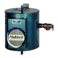
2. Install the combination temperature and pressure safety relief valve in the tapping
provided. Note that this is required by law for safety considerations.
Install into provided tapping Manual Release Lever
Temperature Probe
Outlet to floor drain
3. Install a relief valve overflow pipe to a nearby floor drain.
NOTE: Relief valve discharge piping limitations:
a. Termination to be plain end (no threads) and 6-inches above the drain.
b. Maximum 30-feet.
c. Maximum four (4) elbows.
d. No reduction in line size.
e. No valve of any type to be installed between the relief valve and tank or in the
drain line.
FILLING THE HEATER
1. Open the valve to the cold water inlet and allow the heater and piping system to
completely fill, as indicated by a steady flow of water through the process outlet.
NOTE: Flush the tank at full flow for 10 minutes prior to putting into service.
ELECTRICAL INSTALLATION
1. Enter the base through the factory cut KO’s with properly sized feeder leads, See
Wiring Chart. Single-phase installations require two (2) leads. All Hubbell 3-phase
heaters are intended for use with a 3-wire delta system plus ground. No neutral is