10
required. For a 4-wire plus ground system, install 3 legs of power plus the ground and
terminate the neutral leg.
2. Install these power leads into the box lugs on the power distribution block or magnetic
contactor, as required.
3. Connect incoming ground wire to ground lug supplied.
4. Check for proper grounding.
5. All other electrical connections are made at the factory; therefore, no other electrical
connections are necessary.
6. Check all connections, including factory connections, for tightness.
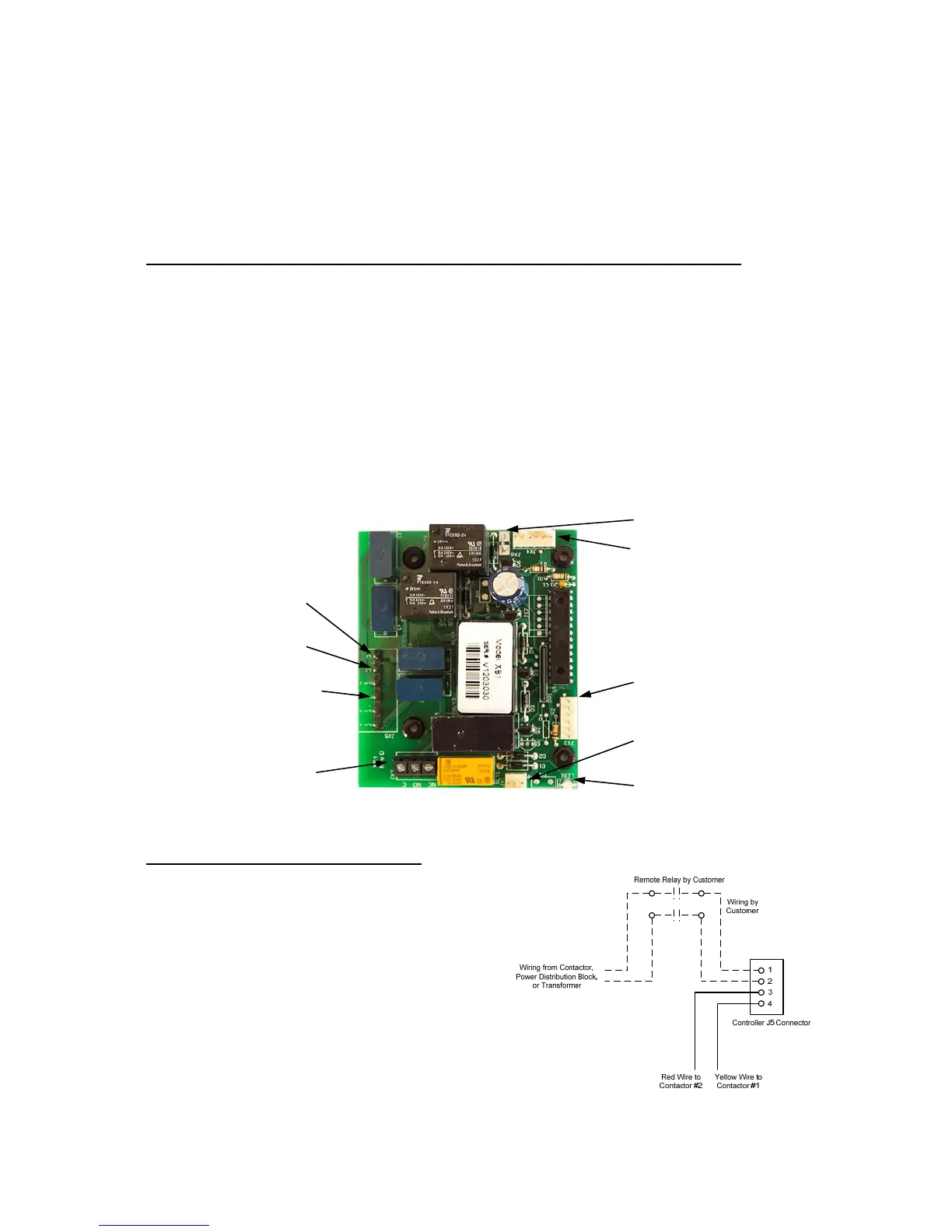
OPTIONAL XB1 EXPANSION BOARD (used for temperature alarm / interlock)
1. If desired, the XB1 can be used as an alarm relay or a temperature interlock at a
setpoint other than the water temperature setpoint on the water heater.
2. If the XB1 is not factory installed, mount the XB1 to the control panel and connect the
XB1 to the T1000 control board with the factory supplied cable between JX4 on the
XB1 and J1 and J4 on the T1000 and connect the ground between JX6 on the XB1
and J8 on the T1000.
3. Make connections as required to the relay terminal block. When the temperature drops
below the XB1 setpoint the relay is open between Normally Open (NO) and Common
(C) and the LED will flash green. When the temperature is above the XB1 setpoint the
relay is closed between NO and C and the LED will be solid green. Use NO and C for
low temperature interlock or high temperature alarm. Use Normally Closed (NC) and C
for low temperature alarm. A red LED indicates an error.
Note: Once the XB1 is connected to the T1000 control board, an additional menu option will
be available to set the low temperature setpoint. See Section III.
FOR REMOTE ON/OFF CONTROL
To remotely control the On / Off operation of the
heater, it is recommended that a DPST switch or
relay (by others) be used to break both power legs
(white and black wires) connected to the top two
terminals of the J5 connector on the control board.
See diagram at right.
Use a NC (Normally Closed) relay to turn the
heater ON when energizing the relay coil or to turn
the heater OFF when de-energizing the relay coil.
Use a NO (Normally Open) relay to turn the heater
OFF when energizing the relay coil or to turn the
heater ON when de-energizing the relay coil.
Note: Alarm Rating (resistive):
Max.: 5A @ 120VAC
5A @ 24VDC
(JX5 L1) Power Wire
(Common, White)
(JX5 L2)Power Wire
(Black)
(JX5) (4) Connections
for Additional Circuit
Firing
(JX2) Low Temp.
Relay Terminal Block
(JX4) Connection to
T1000
(JX3) To be used as
T1000 J1 Connection
(JX1) To be used as
T1000 J4 Connection
LED
(JX6) Ground
 Loading...