11
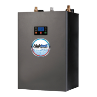
OPTIONAL REMOTE ALARM CONTACTS
1. If desired, the control board can be wired to a remote alarm to indicate a reset fault
condition. These fault conditions include over-temperature, no probe, and low water
(when the configuration is set to manual reset).
2. This alarm can be wired to the J4 connector on the control board as shown below. To
facilitate this installation, an optional adapter, Hubbell P/N PLUG ADAPTER J4, can
be purchased to provide wire connections.
J4 Connector
Note: That when the XB1 expansion board is used, the J4 PLUG ADAPTER should plug
into the JX1 connection on the XB1.
OPTIONAL FIELD CONVERSION FROM SINGLE TO THREE PHASE OR THREE
TO SINGLE PHASE (HD6 and HD16 models in 6, 7, and 9 kW and 208 and 240 volts
only)
1. Find the appropriate diagram for the unit to be converted in the following chart titled
“Wiring Chart”.
2. Re-wire the unit according to the diagram.
NOTE: The wire to be used for internal wiring must conform to SEW-2 or PTFE
(200°C) and must match the wire size currently in use. Contact the factory for
assistance if required.
3. Contact the factory for correct labels. The factory will need the serial number for
proper identification.
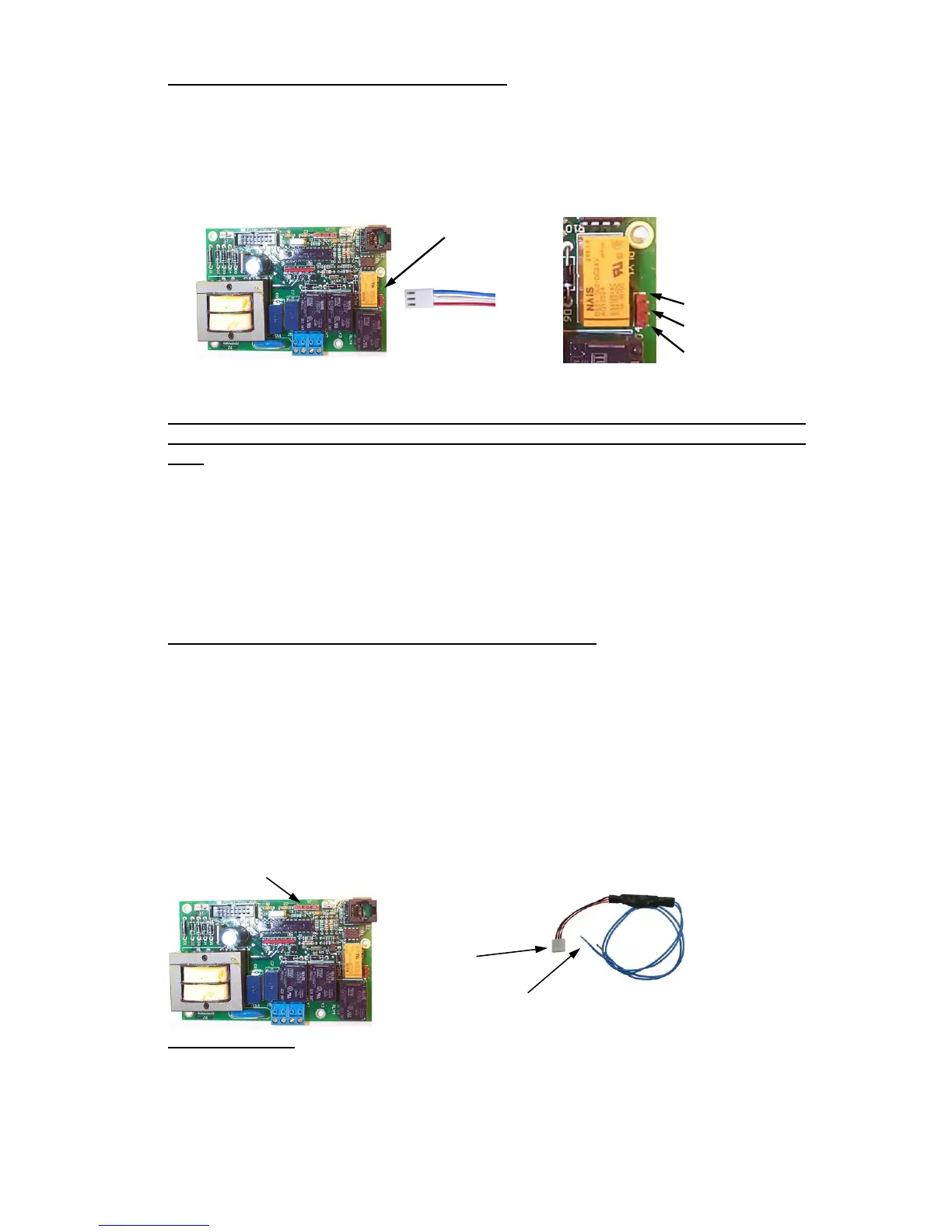
OPTIONAL 24-VOLT HEATER INTERLOCK ADAPTER
1. If desired, the heater can be wired to operate only when supplied with a 24-volt signal
through the heater interlock adapter. When no 24-volt signal is supplied through the
heater interlock adapter the heater is interlocked and will not energize. When
interlocked the display will show “ HLd”. The heater will resume normal operation
when a 24-volt signal is re-applied through the heater interlock adapter.
2. To utilize this feature, plug the 24-volt heater interlock adapter into terminal J1 of the
T1000 control board (note: if the XB1 expansion board is used, plug the adapter into
terminal JX3 of the XB1) and verify that the configuration is set to “ H
on”, see the
controller operation section for further detail. The signal can be either AC or DC.
However, if a DC signal is utilized and the interlock feature does not operate, switch
the two 24-volt supply wires at the heater interlock adapter.
J1
To J1
To 24-Volt Signal
FINAL CHECKS
1. Check all connections for tightness.
2. Ensure that all the above steps are completed.
3. Remove the protective outer plastic covering from the sheet metal shell.
4. After the water is heated for the first time, monitor the water temperature as described
in Section III, Annual Inspection.
Note: Rating (resistive)
Max. Switching Power:
60W, 62.5VA
Max. Switching Voltage:
220VDC, 250VAC
Max. Switching Current: 2A
Max. Carr
 Loading...