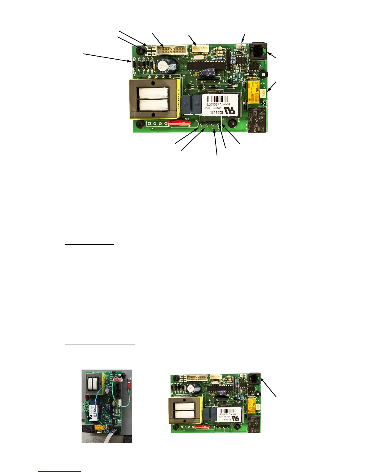
29
Probe Ground (J7) Display Cable Leak Detection Wire (J2)
Ground Wire (J8)
(D1)
Power Wire (Common, White) Connector (J5)
Power Wire (Black) Wire to #1 Contactor (yellow)
Wire to #2 Contactor (red)
Note: Probe connector J3 comes filled with a dielectric gel that should remain in the
connector.
3. Remove four (4) screws securing control board to panel.
4. Remove and replace control board.
5. Reconnect wires disconnected in step 2. NOTE: When reconnecting the ribbon cable,
be sure to have the key on the cable align with the slot in the connector.
6. Connect power to unit.
RELIEF VALVE
1. Disconnect power from unit.
2. Shut off incoming water supply.
3. Attach hose to drain connection.
4. Lift manual release lever on relief valve to let air into system or break union on
outgoing water line.
5. Drain water from tank.
6. Disconnect overflow piping.
7. Unscrew relief valve, remove assembly and replace with new one.
8. Connect overflow piping.
9. Turn on incoming water supply and check for leaks.
10. Connect power to unit.
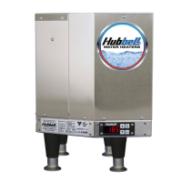
P65SS SENSOR PROBE
1. Disconnect power from the unit.
2. Unplug the P65SS probe connector from J3 and the probe ground from J7 on the
T1000 control board.
Alarm Relay
(J4)
Probe Cable
(J3)
Expansion (J1)
Probe
Connection
(J3)