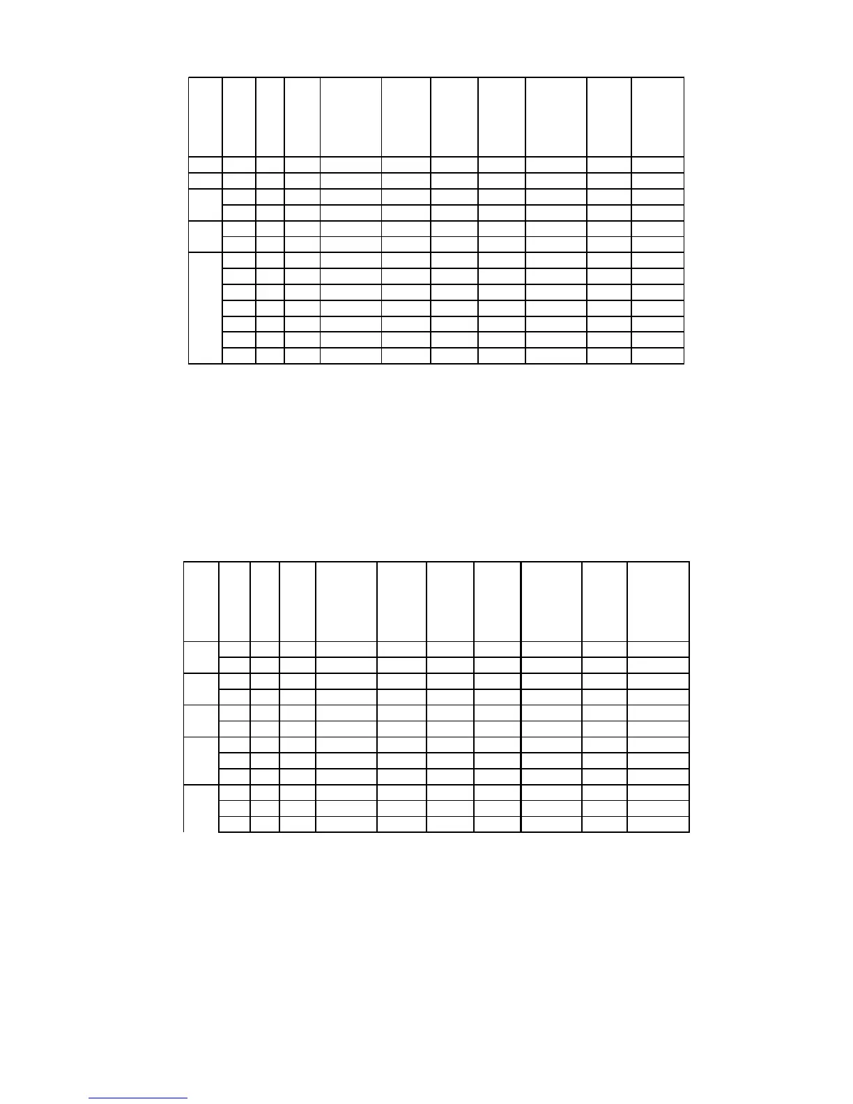
J3 Wiring Chart
kW Volt Ph
Unit
Amp
Draw
Phase-
Phase
Resistance
(Ohms)
Min.
Feed
Breaker
or Fuse
Size
Internal
Power
Wire
Size
Element
Jumper
Wire
Size
Copper
Power Feed
Wire Size
Conduit
Size
Diagram
2.9 120 1 23.8 5.0 30 12 12 10 ½" 4
5.7 120 1 47.5 2.5 60 10 12 6 ¾" 4
208 1 47.6 4.4 60 10 12 6 ¾" 4
208 3 27.5 8.7 35 12 12 8 ½" 10 (NT)
208 1 51.9 4.2 65 10 12 6 ¾" 4
208 3 28.8 8.3 40 12 12 8 ½" 10 (NT)
240 1 47.5 5.1 60 10 12 6 ¾" 4
240 3 27.4 10.1 35 12 12 8 ½" 10 (NT)
277 1 41.2 6.7 55 10 12 6 ¾" 4 (WT)
380 3 16.8 25.3 25 12 12 12 ½" 14
415 3 15.9 30.2 20 12 12 12 ½" 14
480 3 13.7 40.4 20 12 12 14 ½" 14
600 3 11.0 63.2 15 12 12 14 ½" 14
9.9
10.4
11.4
J3 Wiring Chart Notes:
1. Power feed wire sizing is based on using 75°C Cu THHN wire with feeder branch
protection rated at 125%.
2. Internal wire sizing is based on using 200°C SEW-2 or PTFE wiring in a raceway
with an ambient temperature up to 60°C.
3. Normal phase-to-phase resistance tolerance is ±5%.
4. 277, 380,415, 480, and 600-volt phase-to-phase resistance values are shown with the
transformer disconnected.
J4 Wiring Chart
kW Volt Ph
Unit
Amp
Draw
Phase-
Phase
Resistance
(Ohms)
Min.
Feed
Breaker
or Fuse
Size
Internal
Power
Wire
Size
Element
Jumper
Wire
Size
Copper
Power Feed
Wire Size
Conduit
Size
Diagram
208 1 54.1 3.8 70 8 8 4 1" 4
208 3 31.2 7.7 40 8 8 8 ½" 10 (NT)
220 1 57.3 3.8 75 8 8 4 1" 4
220 3 33.1 7.7 45 8 8 8 ½" 10 (NT)
230 1 59.8 3.8 75 8 8 4 1" 4
230 3 34.5 7.7 45 8 8 8 ½" 10 (NT)
240 1 62.5 3.8 80 8 8 4 1" 4
240 3 36.1 7.7 50 8 8 8 ½" 10 (NT)
480 3 18.0 30.7 25 12 12 10 ½" 10 (WT)
208 3 75.0 3.2 95 6 8 3 1" 10 (NT)
240 3 65.0 4.3 85 8 10 4 1" 10 (NT)
480 3 32.5 17.1 45 12 12 8 ½" 10 (WT)
13.8
11.3
12.6
15
27
J4 Wiring Chart Notes:
1. Power feed wire sizing is based on using 75°C Cu THHN wire with feeder branch
protection rated at 125%.
2. Internal wire sizing is based on using 200°C SEW-2 or PTFE wiring in a raceway
with an ambient temperature up to 60°C.
3. Normal phase-to-phase resistance tolerance is ±5%.
4. 480-volt phase-to-phase resistance values are shown with the transformer disconnected.