7
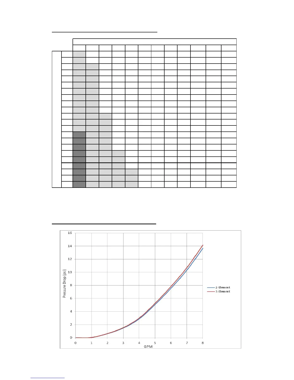
Tankless Water Heater Maximum Flow Rates:
5°F 10°F 20°F 30°F 40°F 50°F 60°F 70°F 80°F 100°F 120°F 140°F
8
10.9 5.5 2.7 1.8 1.4 1.1 0.9 0.8 0.7 0.5 0.5 0.4
11
15.0 7.5 3.8 2.5 1.9 1.5 1.3 1.1 0.9 0.8 0.6 0.5
12
16.4 8.2 4.1 2.7 2.1 1.6 1.4 1.2 1.0 0.8 0.7 0.6
13
17.8 8.9 4.4 3.0 2.2 1.8 1.5 1.3 1.1 0.9 0.7 0.6
14
19.1 9.6 4.8 3.2 2.4 1.9 1.6 1.4 1.2 1.0 0.8 0.7
15
20.5 10.3 5.1 3.4 2.6 2.1 1.7 1.5 1.3 1.0 0.9 0.7
16
21.9 10.9 5.5 3.6 2.7 2.2 1.8 1.6 1.4 1.1 0.9 0.8
18
24.6 12.3 6.2 4.1 3.1 2.5 2.1 1.8 1.5 1.2 1.0 0.9
20
27.3 13.7 6.8 4.6 3.4 2.7 2.3 2.0 1.7 1.4 1.1 1.0
21
28.7 14.4 7.2 4.8 3.6 2.9 2.4 2.1 1.8 1.4 1.2 1.0
24
32.8 16.4 8.2 5.5 4.1 3.3 2.7 2.3 2.1 1.6 1.4 1.2
25
34.2 17.1 8.5 5.7 4.3 3.4 2.8 2.4 2.1 1.7 1.4 1.2
27
36.9 18.5 9.2 6.2 4.6 3.7 3.1 2.6 2.3 1.8 1.5 1.3
30
20.5 10.3 6.8 5.1 4.1 3.4 2.9 2.6 2.1 1.7 1.5
31
21.2 10.6 7.1 5.3 4.2 3.5 3.0 2.6 2.1 1.8 1.5
33
22.6 11.3 7.5 5.6 4.5 3.8 3.2 2.8 2.3 1.9 1.6
36
24.6 12.3 8.2 6.2 4.9 4.1 3.5 3.1 2.5 2.1 1.8
40
27.3 13.7 9.1 6.8 5.5 4.6 3.9 3.4 2.7 2.3 2.0
42
28.7 14.4 9.6 7.2 5.7 4.8 4.1 3.6 2.9 2.4 2.1
48
32.8 16.4 10.9 8.2 6.6 5.5 4.7 4.1 3.3 2.7 2.3
50
34.2 17.1 11.4 8.5 6.8 5.7 4.9 4.3 3.4 2.8 2.4
54
36.9 18.5 12.3 9.2 7.4 6.2 5.3 4.6 3.7 3.1 2.6
Maximum Flow Rate (GPM) at Temperature Rise (°FΔT)
Power (kW)
1. Shaded values indicate that a High Flow (HX) unit is required.
2. Blank values indicate that the flow rate will exceed the flow capability of the flow meter.
3. For alternate power (kW) values, the maximum flow rate can be calculated using the
formulas on the following page.
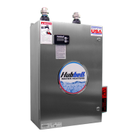
Tankless Low Flow Pressure Drop Chart (TX):