32
SECTION VI – SERVICING & REPLACEMENT OF PARTS
WARNING: Serious bodily injury or death may occur if the following warnings are
ignored.
• This following portion of this section is intended for use by a QUALIFIED
ELECTRICIAN OR PLUMBER.
•
All circuit breakers must be turned off at the main panel before the cover of the unit
is removed.
• When any maintenance is performed on the water heater that may introduce air into
the unit, it is important to purge the air out of the lines before allowing the unit to
power up. See Checking for Leaks and Purging Air in Section III.
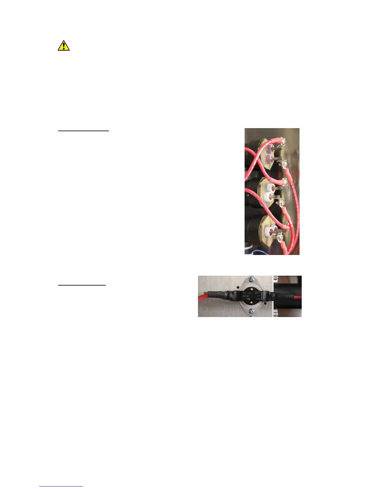
Heating Element:
• Disconnect power.
• Shut off cold water inlet and hot water outlet valves.
• Drain unit.
• Remove cover.
• Disconnect the RED power leads from the top of the
element to be replaced.
• Unscrew the element from the heating chamber coupling.
• Install the replacement heating element by screwing it into the
heating chamber coupling.
NOTE: Verify that the o-ring is installed onto the heating
element prior to installation.
• Re-connect the power leads to the element terminals.
• Re-install cover.
• Open the cold water inlet and hot water outlet valves.
• Bleed air from the unit. See Checking for Leaks and Purging
Air in Section III.
• Turn on power.
Hi-Limit Switch:
• Disconnect power.
• Remove cover.
• For single-phase models, disconnect the
leads from the heating element and power
distribution block that connect to the hi-limit switch to be replaced. For three-phase
units, disconnect the wires from the hi-limit switch to be replaced.
NOTE: The replacement hi-limit switch comes with power leads attached. For single-
phase units, power leads should not be disconnected from the hi-limit switch. For
three-phase units, disconnect the attached power leads on the replacement piece.
• Remove the two (2) screws securing the hi-limit switch to the heating chamber cover.
• Remove the hi-limit switch.
• Spread a pea sized amount of the conductive thermal paste included with the
replacement kit on the back of the hi-limit switch (the portion to be installed against the
heating chamber tube).
• Install the hi-limit switch to the heating chamber cover with the two (2) screws
previously removed.
• For single-phase units, connect the supplied power leads to the heating element and the
power distribution block. For three-phase units, connect the wires previously
disconnected in the prior step.
• Re-install cover.
• Turn on power.