2624 2624HS 2628 2630 Series Tooling Alcoa Fastening Systems
12
5. NOTE: Do not remove hydraulic hoses from tool
unless replacing hoses. If necessary to remove
hoses, uncover hose fittings by sliding plastic
shrouds back.
6. NOTE: Use the following steps only if the Switch,
Wire or Connector needs repair.
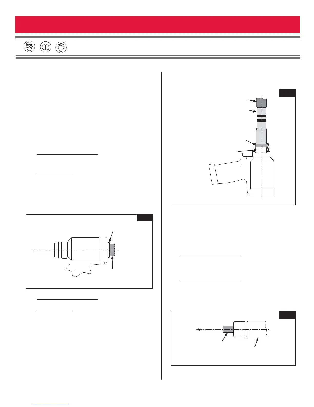
Remove Retaining Nut and Locking Ferrule from
Strain Relief (20). Loosen Set Screw (37) and
remove Switch (21). Loosen and remove the two
wires from the switch. Remove cord from tool.
Disassemble electrical connector (110686).
7. Models 2624, 2628, 2630:
(Figures 8, 10 & 11)
Remove Retaining Ring (17), cover plate (16) and
Locking Disk (18).
Model 2624HS: (Figure 9)
Remove Screws (31), Retainer (30) and Locking
Disk (18).
8. Insert Hex Key 126981 (shipped with tool) in End
Cap (15)
(Figure 2). Using a wrench, unscrew End
Cap from Cylinder.
9. Models 2624, 2628, 2630:
(Figures 8, 10 & 11)
Remove O-ring (9) and Back-up Ring (8)
Model 2624HS: (Figure 9)
Remove O-ring (9), Back-up Ring (8), Retaining
Ring (36), Washer (35), Polyseal (34) and Wiper
seal (33).
10. Remove Dump Valve (19) from rear of Cylinder.
11. Slide Spacer over Piston and thread on Piston
Assembly Tool. Using a press push Front Gland
and Piston assemblies out of the back of the
Cylinder.
(Figure 3)
12. Remove Piston Assembly Tool and Spacer (Figure
3)
.
13. Slide Front Gland (11) off of Piston (4) and remove
Wiper (6), Wiper Housing (7), Back-up Ring (8), O-
ring (9) and Polyseal (10)
(Figures 8-11).
14. Remove GLYD Ring (13) from Piston (4)(Figure 5).
15. Models 2624, 2628, 2630:
(Figures 8, 10 & 11)
Hold Piston (4) in a vise with soft jaws and remove
Ejector Gland Assembly (22) with Hex Key 122048
16. Models 2624, 2628, 2630: (Figures 4, 8, 10 & 11)
Remove from Gland, Ejector Rod (29), Washer
(23), O-rings (24), Wiper (26) Quad-Ring (28) and
Back-up Ring (27).