2624 2624HS 2628 2630 Series Tooling Alcoa Fastening Systems
13
ASSEMBLY All Models
For component identification and Parts Lists, refer to
Figures 8-12.
NOTE: Clean components with mineral spirits, or similar
solvent. Inspect for wear/damage and replace as neces-
sary. Replace all seals of disassembled components. Use
O-rings, Quad-Rings and Back-up Rings in Service Parts
Kit 2620KIT (all models) and 2620-PTKIT (all models).
Smear LUBRIPLATE 130AA or PARKER-O-LUBE on O-
rings, Quad-Rings, Back-up Rings and mating parts to
ease assembly. Assemble tool taking care not to damage
O-rings, Quad-Rings, or Back-up Rings.
1. Models 2624, 2628, 2630:
(Figures 8, 10 & 11)
Install Back-up Ring (27), Quad-Ring (28), Wiper
(26), O-rings (24), Washer (23) and Ejector Rod (29)
into Ejector Gland (25).
2. Models 2624, 2628, 2630:
(Figures 4, 8, 10 & 11)
Hold Piston (4) in a vise with soft jaws and install
assembled Ejector Gland (22). Use Hex Key 122048
to tighten.
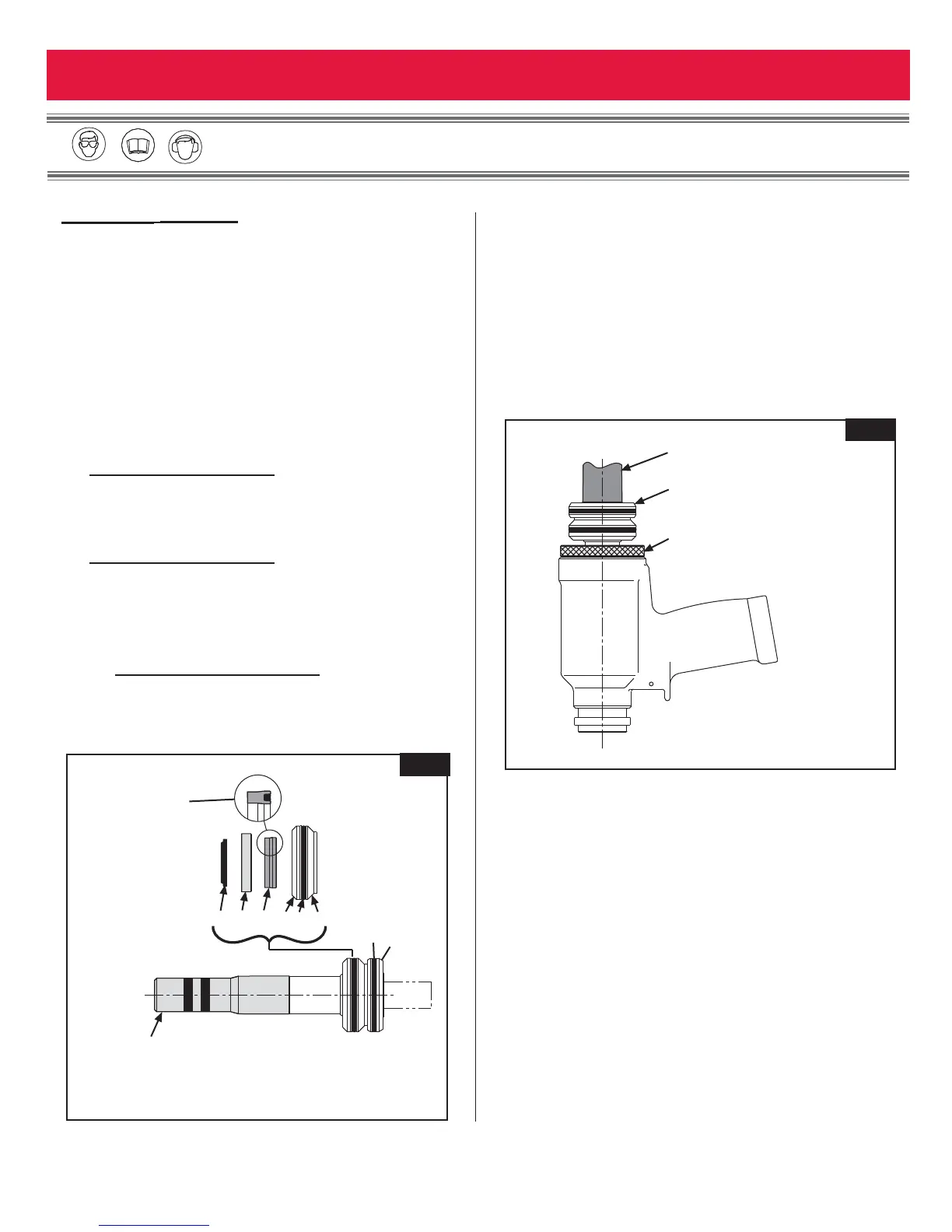
3. Thread Piston Assembly Tool, onto Piston (4)
(Figure
5)
. Note: Do not install Spacer.
4. Install GLYD Ring (13) onto Piston (4) (Figure 5).
5. Install Polyseal (10), O-ring (9), Back-up Ring (8),
Wiper Housing (7) and Wiper (6) into Front Gland
(11)
(Figure 5).
6. Lubricate Piston Assembly Tool and Piston, then
slide assembled Gland (11) over Piston Assembly
Tool onto Piston
(Figure 5).
7. Thread GLYD Ring Insertion Tool into the back of the
Cylinder
(Figure 6).
8. Using a press, push Piston and Front Gland
Assemblies into the back of Cylinder (5).
(Figure 6)
9. Remove Piston Assembly Tool (Figure 5).
10. Remove the GLYD Ring Insertion Tool from the back
of the Cylinder
(Figure 6).
11. From the rear of Cylinder, install Dump Valve (19)
with the four flats facing the rear of the tool
(Figures 8-11).
(continued)