2624 2624HS 2628 2630 Series Tooling Alcoa Fastening Systems
14
12. Models 2624, 2628, 2630: (Figures 8, 10 & 11)
Install O-ring (9) and Back-up Ring (8) on End Cap
(15).
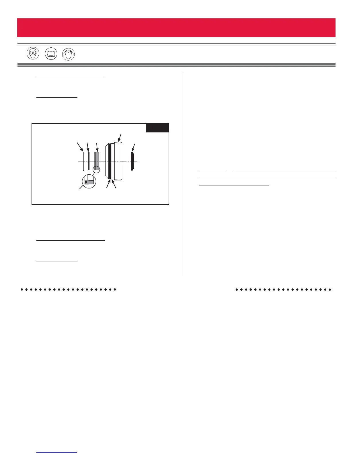
Model 2624HS: (Figures 7 & 9)
Install Back-up Ring (8), O-ring (9), Wiper Seal (33),
Polyseal (34), Washer (35) and Retaining Ring (36)
into End Cap (15).
13. Insert Hex Key into the End Cap (15). Using a
wrench thread the End Cap into the back of the
Cylinder and tighten
(Figure 2).
14. Models 2624, 2628, 2630:
(Figures 8, 10 & 11)
Install Locking Disk (18), Cover Plate (16) and
Retaining Ring (17).
Model 2624HS:
(Figure 9)
Install Locking Disk (18), Barbed Retainer (30),
Screws (31) and Deflector (32).
15. If removed, reinstall Electrical Connector
(Figure 12).
16. NOTE: If switch or wire have been removed,
replace as follows:
Slide Retaining Nut and Ferrule onto Electrical Wire.
Feed Wire through Handle and pull out through the
Trigger Switch hole. Attach Wires to Switch (21) and
push the assembly back into the Handle. Tighten
Screw (37) to hold Trigger Switch in place. Slide
Ferrule into Strain Relief Housing, then thread and
tighten Retaining Nut
(Figures 8-12).
17. If removed, install one hydraulic Hose in Handle port
marked "P" and one in port marked “R”.
CAUTION:
Do not use TEFLON tape on pipe
threads.(See GOOD SERVICE PRACTICES section of
this manual, pages 10-11)
18. Install Coupler Nipple 110438, (PULL pressure
hose), Coupler Body 110439, (RETURN pressure
hose) (Figure 12).